Special grinding machine for ground finish of crystal silicon square billet

A grinding and special grinding machine technology, applied in machine tools suitable for grinding workpiece planes, machine tools suitable for grinding workpiece edges, grinding machines, etc., can solve problems such as low production efficiency, poor processing accuracy, and complex processes. Achieve the effect of high production efficiency, good surface quality and improved operating conditions

Inactive Publication Date: 2011-05-25
ZHEJIANG UNIV OF TECH
View PDF0 Cites 0 Cited by
  • Summary
  • Abstract
  • Description
  • Claims
  • Application Information

AI Technical Summary

Problems solved by technology

[0003] In order to overcome the existing disadvantages of using single-side grinding wheel for grinding and multiple clamping when processing crystalline silicon billets, complex process, low production efficiency, poor processing accuracy and high defective rate, the present invention provides a method that does not require Multiple clamping, high production efficiency, high processing precision, and low defective rate special grinding machine for crystalline silicon billet grinding

Method used


Image

  • Special grinding machine for ground finish of crystal silicon square billet
  • Special grinding machine for ground finish of crystal silicon square billet
  • Special grinding machine for ground finish of crystal silicon square billet

Examples


Embodiment 1

[0034] refer to Figure 1-9

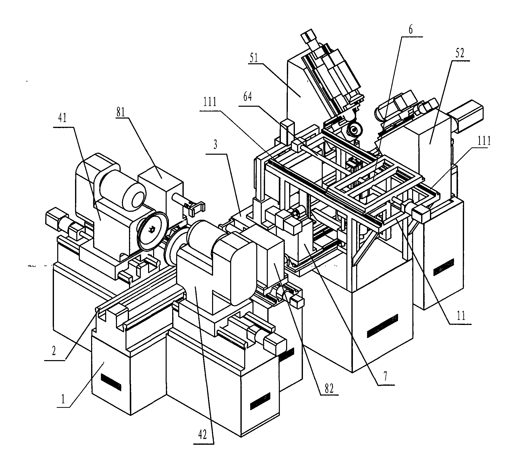
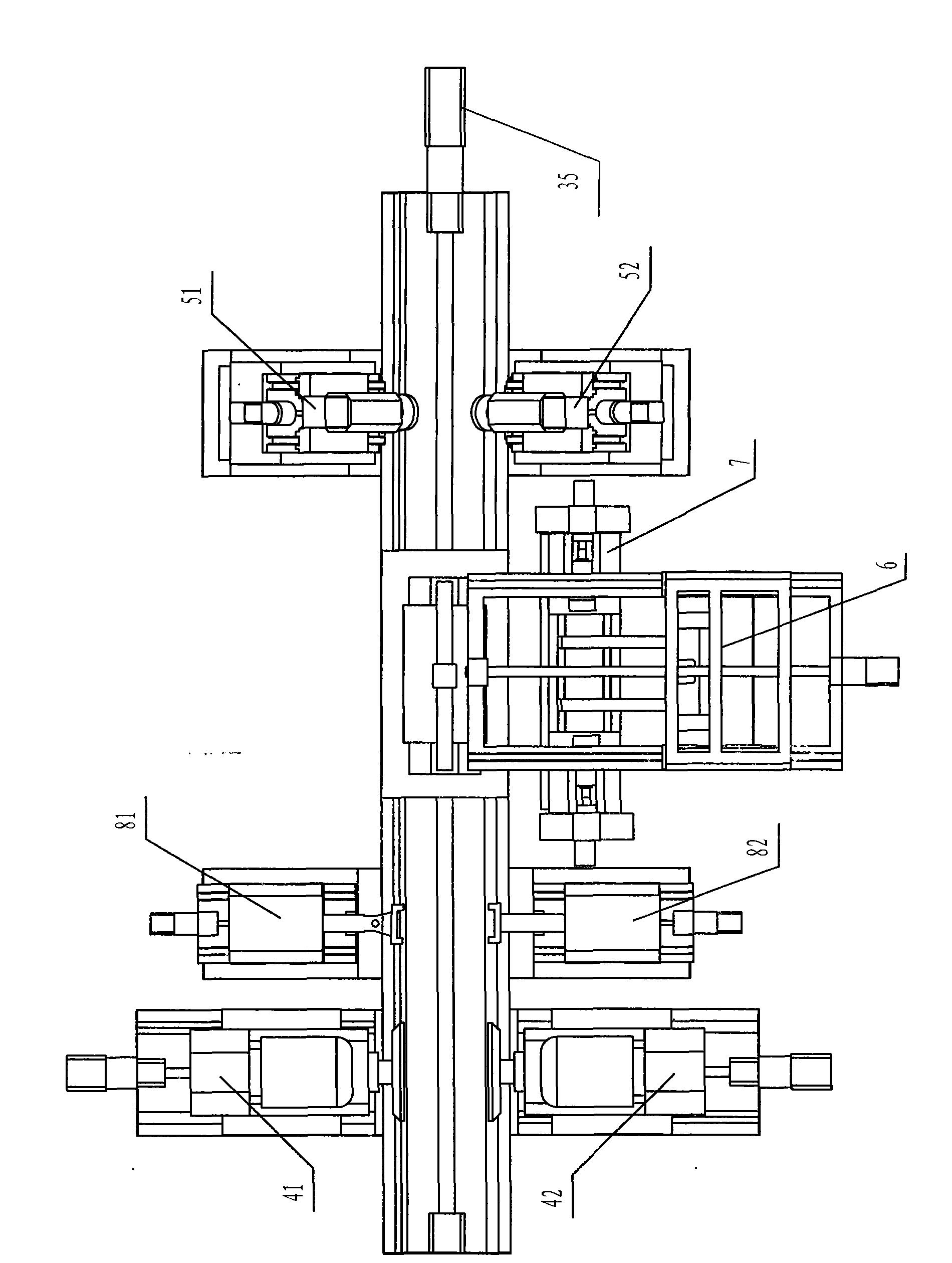
[0035]A special grinding machine for crystalline silicon billet grinding, including a base 1, and the base 1 is provided with:

[0036] The guide rail 2 and the workbench 3 for placing the crystalline silicon billet, the workbench 3 is slidably installed on the guide rail 2, and the workbench 3 is linked with the working motor 35 fixed on the base 1;

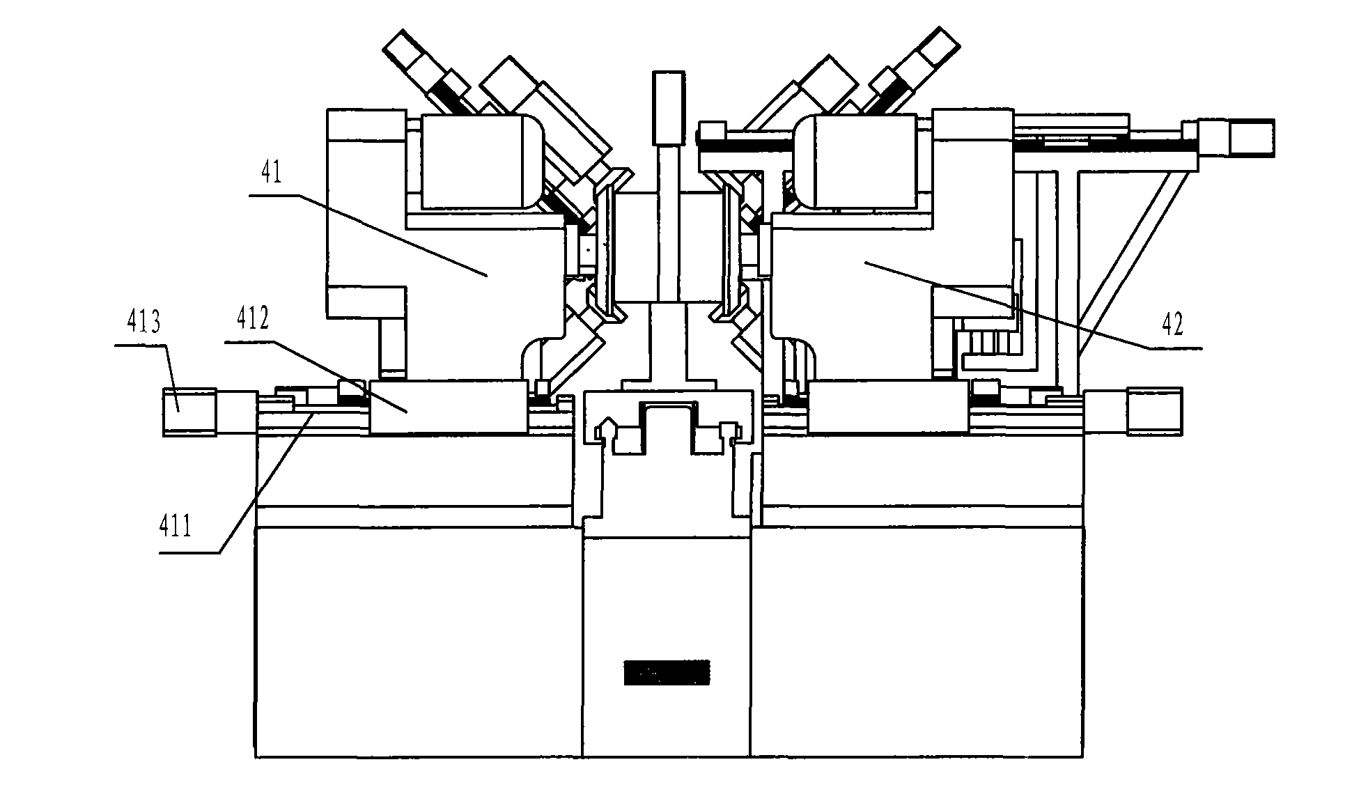
[0037] The first side grinding power head 41 and the second side grinding power head 42 are arranged symmetrically on both sides of the guide rail 2 to grind the two sides of the crystalline silicon billet;

[0038] The first chamfering mechanism 51 and the second chamfering mechanism 52 are arranged symmetrically on both sides of the guide rail 2 to chamfer the four corners of the crystalline silicon billet. The upper chamfering bracket 511, the chamfering bracket 511 is symmetrically equipped with an upper chamfering grinding power head 512 and a lower chamfering grinding power head 513 for cham...

Embodiment 2

[0043] refer to Figure 1-5

[0044] The difference between this embodiment and Embodiment 1 is that: the base 1 is provided with a centering slide rail 813, and a centering slide table 814 is slidably installed on the centering slide rail 813. The positioning block 812 is connected with the centering slide 814 through a horizontal shaft 815, and the centering slide 814 is linked with the motor 816 that drives the centering slide 814 to move through the centering feed mechanism , the centering feed mechanism is a screw mechanism; the first positioning block 812 of the first centering mechanism 81 is hinged to the first horizontal shaft 815 .

[0045] The centering mechanism 81, 82 is arranged between the side grinding power head 41, 42 and the chamfering mechanism 51, 52, and the transfer manipulator 6 is arranged in the centering mechanism 81 , 82 and the chamfering mechanism 51,52. The rest is the same.

Embodiment 3

[0047] refer to Figure 8 , 9

[0048] The difference between the present embodiment and the second embodiment is that the turning mechanism also includes a sliding track 713 fixed on the base 1 and a slide table 714 slidably mounted on the sliding track 713 forward and backward. The clamping claw 711 is rotatably arranged on the slide table 714, and the swing cylinder 712 is fixed on the slide table 714; , promote the cylinder 715 that slide table 714 moves back and forth.

[0049] The clamping claw 711 includes a clamping frame 7111 and an upper clamping piece 7112 and a lower clamping piece 7113 connected with the clamping frame 7111; the upper clamping piece 7112 is fixed with an upper nut, so The lower clamping piece 7112 is fixed with a lower nut 7114, and the thread direction of the upper nut and the lower nut 7114 is opposite; the clamping frame 7111 is fixed with the upper and lower nuts Cooperating screw rod 7115, the thread direction of the upper half of the scr...


PUM


Abstract

The invention relates to a special grinding machine for the ground finish of a crystal silicon square billet, comprising a base on which a guide rail and a worktable are arranged, a first lateral grinding power head, a second lateral grinding power head, a first chamfering mechanism, a second chamfering mechanism, a carrying mechanical hand and an overturning platform. The invention has the advantages that multiple times of clamping are dispensed with, the production efficiency and the machining accuracy are high, and the defective rate is low.

Description

technical field [0001] The invention relates to equipment for mechanically processing silicon electronic materials, in particular to a special grinder for grinding four sides and chamfering of crystalline silicon billets. Background technique [0002] Photovoltaic power generation is a technology that uses the principle of photovoltaic effect of semiconductor materials to directly convert solar radiation energy into electrical energy. With the rapid consumption of global mineral resources and the continuous enhancement of people's awareness of environmental protection, green energy that makes full use of the sun is highly valued. As the main application, crystalline silicon solar cells occupy the vast majority of the solar cell market. The silicon wafer preparation process and technology are developing at a high speed, and the requirements for the processing equipment used are increasing, especially the production efficiency and processing accuracy of the equipment. for high...

Claims


Application Information

Patent Timeline
Patent Type & Authority Patents(China)
IPC IPC(8): B24B9/06B24B7/17
Inventor 欧长劲李兴旺
Owner ZHEJIANG UNIV OF TECH
Why Eureka
Try Eureka