
Power module with double radiators

A technology for power modules and heat sinks, which is applied in electric solid state devices, semiconductor devices, semiconductor/solid state device components, etc., can solve the problem that the heat dissipation requirements of high-power semiconductor chips cannot be met, the heat of semiconductor chips is not dissipated in time, and the power module is affected. Work performance and other issues, to achieve efficient and reliable long-term use, reduce the difficulty of layout manufacturing and welding process, and improve the effect of heat dissipation

Active Publication Date: 2015-06-10
MACMIC SCIENCE & TECHNOLOGY CO LTD
View PDF4 Cites 7 Cited by
  • Summary
  • Abstract
  • Description
  • Claims
  • Application Information

AI Technical Summary

Problems solved by technology

With the development of technology, the power of power devices is getting higher and higher, and the power consumption of semiconductor chips is also gradually increasing. Often, the heat generated by semiconductor chips is also increasing. If the heat of semiconductor chips is not dissipated in time, it will seriously affect Operating performance of the power module
At present, the heat dissipation mechanism of the power module mostly adopts a finned radiator, which is connected to the bottom of the copper substrate, so the semiconductor chip dissipates heat on one side, and the one-sided heat dissipation can no longer meet the heat dissipation requirements of high-power semiconductor chips. Need to adopt new technology to solve the performance of heat dissipation to ensure efficient and reliable long-term use of the module

Method used


Image

  • Power module with double radiators
  • Power module with double radiators
  • Power module with double radiators

Examples


Embodiment Construction

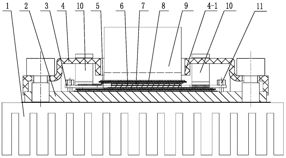
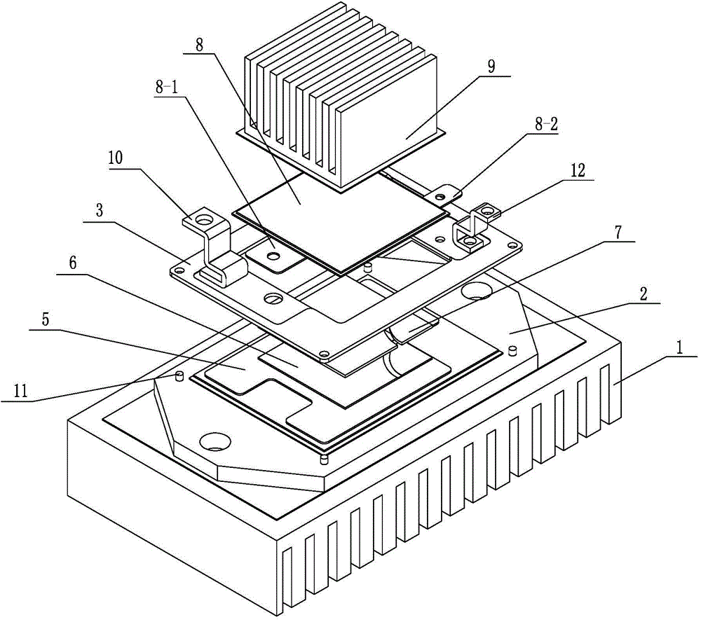
[0011] See figure 1 , 2 As shown, the power module with double heat sinks of the present invention includes a copper substrate 2, a metal-ceramic substrate and a semiconductor chip 6, and the semiconductor chip 6 can be a MOS transistor, an IGBT or a thyristor.

[0012] See figure 1 , 2 As shown, the cermet-clad substrate of the present invention comprises an upper cermet substrate 8 and a lower cermet substrate 5, and the upper cermet substrate 8 and the lower cermet substrate 5 are all composed of a ceramic layer and a metal ceramic layer covering the upper and lower sides of the ceramic layer. Metal layer structure, the underlying cermet substrate 5 is fixed on the copper substrate 2, and the underlying cermet substrate 5 can be welded on the copper substrate 2 by welding, and the copper substrate 2 is fixedly connected to the lower radiator 1, and the copper substrate 2 It can be fixed on the lower radiator 1 with thermal conductive adhesive, the connection area of ​​th...


PUM


Abstract

The invention relates to a power module with double radiators. A lower metal-clad ceramic substrate is fixedly connected with the lower radiator through a copper substrate. A collector of a semiconductor chip is connected with the lower metal-clad ceramic substrate; an emitter of the semiconductor and a gate thereof are connected with an emitter of an upper metal-clad ceramic substrate and a gate thereof, respectively; an upper radiator is fixed to the top of the upper metal-clad ceramic substrate; a printed circuit board which is hollow is mounted on the copper substrate; an emitter outgoing end of the upper metal-clad ceramic substrate and a gate outgoing end thereof are both connected with the printed circuit board; a collector area of the lower metal-clad ceramic substrate is connected with the printed circuit board; the printed circuit board is provided with two electrode holders corresponding to each other and a terminal holder; a housing is mounted on the copper substrate and covers the upper metal-clad ceramic substrate; the electrode holders and the terminal holder penetrate the housing and are disposed on the top of the housing; the housing is provided with a window allowing penetration of the upper radiator. The power module is reasonable in structure, easier to manufacture, lower in manufacturing cost and capable of running efficiently and reliably for a long period of time.

Description

technical field [0001] The invention relates to a power module with double radiators, and belongs to the technical field of heat dissipation of power modules. Background technique [0002] Semiconductor power modules mainly include copper substrates, metal-ceramic substrates, semiconductor chips, electrode terminals and housings. During the working process of the semiconductor power module, the heat generated by the semiconductor chip is transferred to the heat sink below it through the copper substrate to dissipate the heat of the semiconductor chip. With the development of technology, the power of power devices is getting higher and higher, and the power consumption of semiconductor chips is also gradually increasing. Often, the heat generated by semiconductor chips is also increasing. If the heat of semiconductor chips is not dissipated in time, it will seriously affect The working performance of the power module. At present, the heat dissipation mechanism of the power ...

Claims


Application Information

Patent Timeline
IPC IPC(8): H01L23/36H01L23/498
Inventor 张银王晓宝赵善麒
Owner MACMIC SCIENCE & TECHNOLOGY CO LTD
Learn More