Single-coil shunt release

A shunt release, single-coil technology, applied in the direction of automatic disconnection of emergency protection devices, electrical components, circuit devices, etc. The effect of avoiding heat and burning, eliminating the possibility, and improving the energy efficiency of the circuit

Active Publication Date: 2015-06-10
江阴市懿泓电气有限公司
View PDF4 Cites 0 Cited by
  • Summary
  • Abstract
  • Description
  • Claims
  • Application Information

AI Technical Summary

Problems solved by technology

[0005] The technical problem to be solved by the present invention is: in order to solve the problem that the existing shunt release is easy to be burnt because the electromagnet coil cannot be powered off due to the failure of the on-off contact, and the general circuit cannot be maintained after the control circuit breaker is opened. "Shunt state", possible reclosing problem

Method used


Image

  • Single-coil shunt release
  • Single-coil shunt release

Examples


Embodiment 1

[0031] Embodiment one, such as figure 2 as shown,

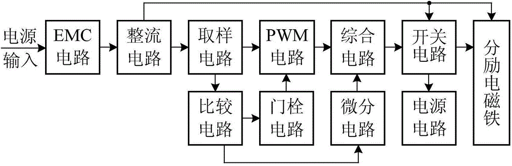
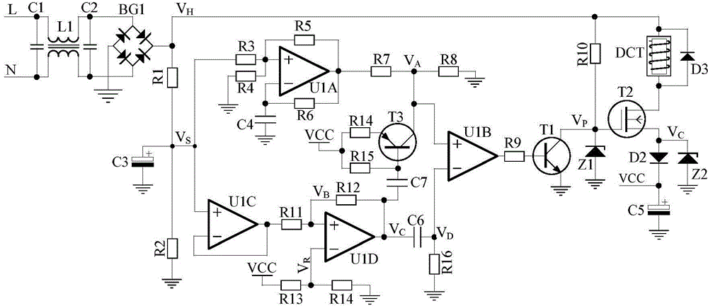
[0032]C1, L1 and C2 form an EMC filter circuit to bidirectionally suppress interference signals from the power grid and the circuit. The input power supply is connected to L and N, and connected to the full-wave rectifier bridge BG1 through the EMC filter circuit. The rectified full-wave voltage is defined as VH. VH is filtered by the voltage dividing sampling circuit composed of R1, R2 and C3 to form a sampling voltage defined as VS.

[0033] VS is transmitted to the PWM circuit composed of R3, R4, R5, R6, C4 and U1A. The duty cycle of the square wave signal output by the PWM circuit is inversely proportional to VS, that is, the higher the VS, the smaller the duty cycle, in order to make the electromagnet The operating voltage is a constant value. The square wave signal output by the PWM circuit is divided by R7 and R8, and sent to the non-inverting input terminal of the integrated circuit, which is defined as VA.

[00...


PUM


Abstract

The invention discloses a single-coil shunt release. The single-coil shunt release comprises an EMC (electro-magnetic compatibility) filtering circuit, a rectifying circuit, a sampling circuit, a PWM (pulse-width modulation) circuit, an integrated circuit, a switch circuit, a comparison circuit, a door pin circuit, a differentiating circuit, a power circuit and a single-coil shunt electromagnet, wherein the EMC filtering circuit is used for restraining interference signals generated from a power grid and an internal circuit in two ways; and the single-coil shunt electromagnet comprises a coil winding and a movable iron core. By the single-coil shunt release, releasing actions do not exist when the voltage of the power grid is lower than nominal voltage by 70%, high-reliability releasing can be guaranteed when the voltage of the power grid is higher than the nominal voltage by 70%, after the single-coil shunt release is released, the releasing state of the single-coil shunt release is always maintained until the voltage of the power grid is removed or is reduced to be below 30%, and possibility of reclosure is stopped effectively. During releasing of the single-coil shunt release, reliable shunt releasing can be implemented by the electromagnet through the maximum power, and the conduction time is quite short; and after releasing of the single-coil shunt release, a small power is applied to the electromagnet so as to maintain the releasing state, heating and overturning of the electromagnet can be avoided effectively, and the electromagnet can also be in a powered-on state for a long time.

Description

technical field [0001] The invention relates to a low-voltage circuit breaker tripping technology, in particular to a single-coil shunt tripper. Background technique [0002] The shunt release is an accessory for remote control and opening. According to GB14148.1-2006 "General Rules for Low-Voltage Switchgear and Control Equipment" and GB14048.2-2008 "Low-Voltage Switchgear and Control Equipment Part 2: Circuit Breakers "Stipulates that when the power supply voltage of the shunt release (measured during the tripping action) is maintained between 70% and 110% of the rated grid voltage, the shunt release should be tripped under all operating conditions of the electrical appliance. button to disconnect the appliance. Referring to the above general principles, it is required that the shunt release can operate reliably when the applied power supply voltage is between 70% and 110% of the rated voltage. When the applied power supply voltage is lower than 70% of the rated voltage,...

Claims


Application Information

Patent Timeline
IPC IPC(8): H02H7/26H02H3/06
Inventor 吴志祥邹一琴许泽刚史建平
Owner 江阴市懿泓电气有限公司
Why Eureka
Try Eureka