Safe recovery system and method for converter flue gas waste heat

A converter flue gas and recovery system technology, which is applied in the direction of manufacturing converters, improving process efficiency, and improving energy efficiency, can solve environmental pollution, high energy consumption, incomplete recovery of flue gas sensible heat, and water resource consumption. Achieve the effect of reducing the possibility of explosion, reducing the possibility of explosion, and eliminating the possibility

Active Publication Date: 2017-08-18
WISDRI ENG & RES INC LTD
View PDF5 Cites 3 Cited by
  • Summary
  • Abstract
  • Description
  • Claims
  • Application Information

AI Technical Summary

Problems solved by technology

This method not only wastes a lot of heat, but also leads to high consumption of water resources, environmental pollution and energy, which seriously restricts the improvement of the energy consumption level of the steelmaking converter process.
In addition, the conventional wet and dry processes are based on ensuring production operation and recovering gas, and basically realize the recovery of chemical energy in the flue gas, but the recovery of sensible heat of the flue gas is not complete, and the flue gas is only cooled by vaporization. Part of the sensible heat of the flue gas is recovered. The difficulty of recovering the sensible heat of the flue gas below 800~900°C is that when the flue gas temperature is lower than 800°C, recovery by conventional methods may cause explosion hazards

Method used


Image

  • Safe recovery system and method for converter flue gas waste heat
  • Safe recovery system and method for converter flue gas waste heat

Examples


Embodiment Construction

[0027] In order to better understand the present invention, the present invention will be further described below in conjunction with the accompanying drawings and specific embodiments.

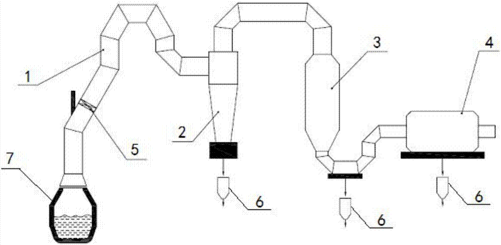
[0028] Such as figure 1 A converter flue gas waste heat safety recovery system shown in the figure includes a waste heat boiler 1, a centrifugal dust removal device 2, a flue gas uniform flow waste heat recovery device 3 and a fine dust removal device 4. The inlet of the waste heat boiler 1 is connected to the flue gas outlet of the converter 7 , the outlet of the waste heat boiler 1 is connected with the gas inlet of the centrifugal dedusting device 2 through the pipe, the gas outlet of the centrifugal dedusting device 2 is connected with the inlet of the uniform flow waste heat recovery device 3 through the pipe, and the outlet of the uniform flow waste heat recovery device 3 is connected with the precision through the pipe The inlet of the dedusting device 4 is communicated, and the outlet...


PUM


Abstract

The invention discloses a safe recovery system for converter flue gas waste heat. The safe recovery system comprises a waste heat boiler, a centrifugal force dust removal device, a flue gas uniform flow waste heat recovery device and a fine dust removal device; an inlet of the waste heat boiler communicates with a flue gas outlet of a converter; an outlet of the waste heat boiler communicates with a gas inlet of the centrifugal force dust removal device; a gas outlet of the centrifugal force dust removal device communicates with an inlet of the uniform flow waste heat recovery device; an outlet of the uniform flow waste heat recovery device communicates with an inlet of the fine dust removal device; and a plurality of swirlers are arranged in the waste heat boiler. The invention further discloses a safe recovery method for the converter flue gas waste heat. The system and the method have the beneficial effects that the swirlers break boundary layers of flue gas flows in the waste heat boiler, enhance disturbance and mixing of the gas flows and promote rapid mixing of CO in flue gas and O2 in the air sucked by a furnace opening so that the CO in the flue gas can be subjected to complete combustion reaction above the spontaneous ignition point of the CO, mixed gas discharged out from the waste heat boiler is outside the explosion limit range, and therefore the possibility of explosion of the flue gas in the subsequent treatment process can be greatly reduced.

Description

technical field [0001] The invention relates to the technical field of waste heat recovery of converter flue gas, in particular to a system and method for safe recovery of waste heat of converter flue gas. Background technique [0002] During the oxygen blowing smelting process of the converter, a large amount of high-temperature flue gas containing carbon monoxide and iron-containing dust will be produced. The flue gas temperature is as high as 1450°C, the average CO content in the flue gas can reach 70%, and its calorific value is 8000kJ / Nm 3 ;The dust content of flue gas is 80~150g / Nm 3 . If the flue gas is released arbitrarily after being released from the furnace, it will not only pollute the environment, but also waste a lot of energy and useful substances. Therefore, both in terms of environmental governance and energy recovery, converter flue gas must be purified and recycled. [0003] Due to the periodic operation of the converter, the flue gas composition, flue...

Claims


Application Information

Patent Timeline
Patent Type & Authority Applications(China)
IPC IPC(8): C21C5/40
CPCC21C5/40Y02P10/25
Inventor 刘攀徐海伦盖东兴
Owner WISDRI ENG & RES INC LTD
Why Eureka
Try Eureka