
Switch capacitance access high frequency bi-directional DC (direct current) transformer and control method thereof

A bidirectional DC, switched capacitor technology, applied in the direction of converting DC power input to DC power output, regulating electrical variables, control/regulating systems, etc., can solve large circulating current, mismatch between DC voltage and transformer ratio, and high current stress problems, to achieve the effect of improving reliability, facilitating rapid recovery, and reducing circulating currents

Active Publication Date: 2015-06-10
TSINGHUA UNIV +1
View PDF5 Cites 29 Cited by
  • Summary
  • Abstract
  • Description
  • Claims
  • Application Information

AI Technical Summary

Problems solved by technology

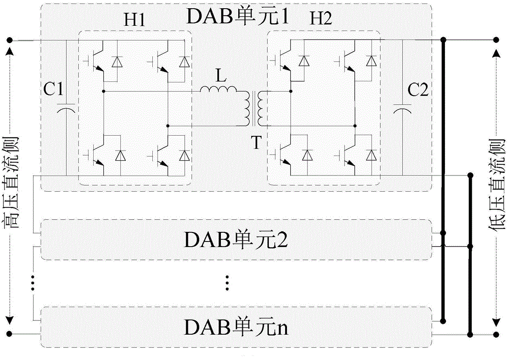
In the process of energy transmission, when the DC voltage at both ends does not match the transformation ratio of the transformer, there will be a large circulating current, which will lead to a large current stress and low efficiency. This is also the technical bottleneck that currently limits the large-scale application of DAB.
However, when the dual-active full-bridge (DAB)-based multiple DC transformer solution is used for system-level DC networking, the DC voltage at both ends of each sub-unit does not match the transformation ratio of the transformer due to fluctuations in the DC bus voltage. operating efficiency

Method used


Image

  • Switch capacitance access high frequency bi-directional DC (direct current) transformer and control method thereof
  • Switch capacitance access high frequency bi-directional DC (direct current) transformer and control method thereof

Examples


Embodiment Construction

[0022] The specific embodiments of the present invention will be further described below in conjunction with the technical scheme of the present invention and the accompanying drawings.

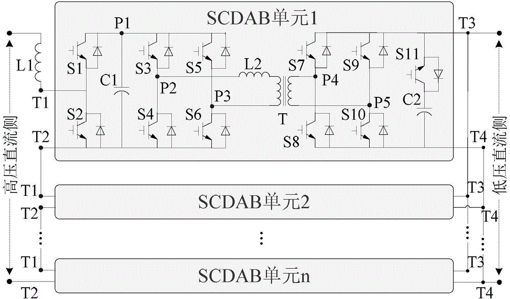
[0023] The topological structure of the high-frequency link bidirectional DC transformer with switched capacitor access of the present invention is as figure 2 Shown. The two-way DC transformer is mainly composed of n identical DC converter units SCDAB1, SCDAB2, ... SCDABn, where n is any positive integer; the first connecting terminal T1 of the high-voltage side of the first DC converter unit SCDAB1 is connected to the DC auxiliary inductor L1 The positive pole of the high-voltage DC side is connected; the second connection terminal T2 of the high-voltage side of the m-th DC converter unit SCDABm is connected to the first connection terminal T1 of the high-voltage side of the m+1-th DC converter unit SCDABm+1, 1≤m <n; The second connecting terminal T2 of the high-voltage side of the n-th DC co...


PUM


Abstract

The invention discloses a switch capacitance access high frequency bi-directional DC (direct current) transformer and belongs to the field of the electric power technology; the switch capacitance access high frequency bi-directional DC transformer is mainly composed of n pieces of DC converter units serially connected in a port and connected in parallel in another port, the DC converter units are the same and n is any positive integer; each DC converter unit is composed of eleven semiconductor switches, two DC capacitors, one high frequency inductor and one high frequency transformer; k pieces of DC converter units in n pieces of DC converter units are in redundancy work state; under normal circumstances, the high voltage sides of the n-k pieces of DC converter units are serially connected to the high voltage DC side while the low voltage sides are connected to the low voltage DC side in parallel; any DC converter unit in redundancy work state can be adopted for working while any DC converter unit has damage or fault for the interior; the semiconductor switches of all DC converter units are turned off while the high voltage DC side or the low voltage DC side has short-circuit fault, and the capacitor voltage is kept. The system circulation is reduced, the fault treatment and redundancy technology are simplified and the reliability is improved.

Description

Technical field [0001] The invention belongs to the technical field of electric power, and relates to solid-state transformers, and in particular to a high-frequency link bidirectional DC transformer with switched capacitor access. Background technique [0002] In the DC grid, due to the maturity of the fully-controlled voltage source converter (VSC) technology, flexible DC transmission technology has developed rapidly. Compared with traditional DC transmission technology, flexible DC transmission does not need to resort to AC grid commutation, there is no problem of commutation failure, and can supply power to passive systems; pulse width modulation (PWM) technology is adopted, and the voltage and current harmonic content are relatively low. Less, can reduce or omit the filtering link, and occupy a smaller area; in addition, the fully-controlled VSC has flexible control, which can quickly and independently control active and reactive power, and the power flow can be adjusted in ...

Claims


Application Information

Patent Timeline
Patent Type & Authority Applications(China)
IPC IPC(8): H02M3/335H02H7/12
Inventor 赵彪宋强刘文华刘国伟赵宇明姚森敬
Owner TSINGHUA UNIV
Learn More