
Super-magnetostrictive thin film type sound sensor

A giant magnetostrictive, sound sensor technology, applied in the field of electrical communication, can solve the problems of failing to solve the sound sensor, increasing the bandwidth, failing to more effectively improve the stability, sensitivity, and accuracy of the sound sensor, and achieving sensitivity unimpaired effect

Inactive Publication Date: 2015-06-10
ANHUI UNIV OF SCI & TECH
View PDF9 Cites 1 Cited by
  • Summary
  • Abstract
  • Description
  • Claims
  • Application Information

AI Technical Summary

Problems solved by technology

[0004] At present, sound sensors are mostly improved in structure. For example, the patent application number 200510035114.0 proposes a capacitive micro-electromechanical structure sound sensor. A series of through holes are arranged on the circumference of the sound hole on the back plate to increase the broadband. Suppress the noise in the low-frequency band below 300Hz; also for example, the patent of application number 201110120750.9 proposes a sensor, which is to protrude a plurality of stoppers on the opposite surface of the diaphragm to prevent the adhesion of the diaphragm; however, due to the determination of the stability of the sound sensor, The key factor of sensitivity, accuracy and other characteristics is the sensitive element, that is, the vibrating membrane that perceives the sound. Therefore, the patents with application numbers 200510035114.0 and 201110120750.9 failed to solve the problems of stability, sensitivity and accuracy of the sound sensor. The technical problems of the sensitive components of the sound sensor, thus failing to improve the stability, sensitivity and accuracy of the sound sensor more effectively

Method used


Image

  • Super-magnetostrictive thin film type sound sensor
  • Super-magnetostrictive thin film type sound sensor
  • Super-magnetostrictive thin film type sound sensor

Examples


Embodiment Construction

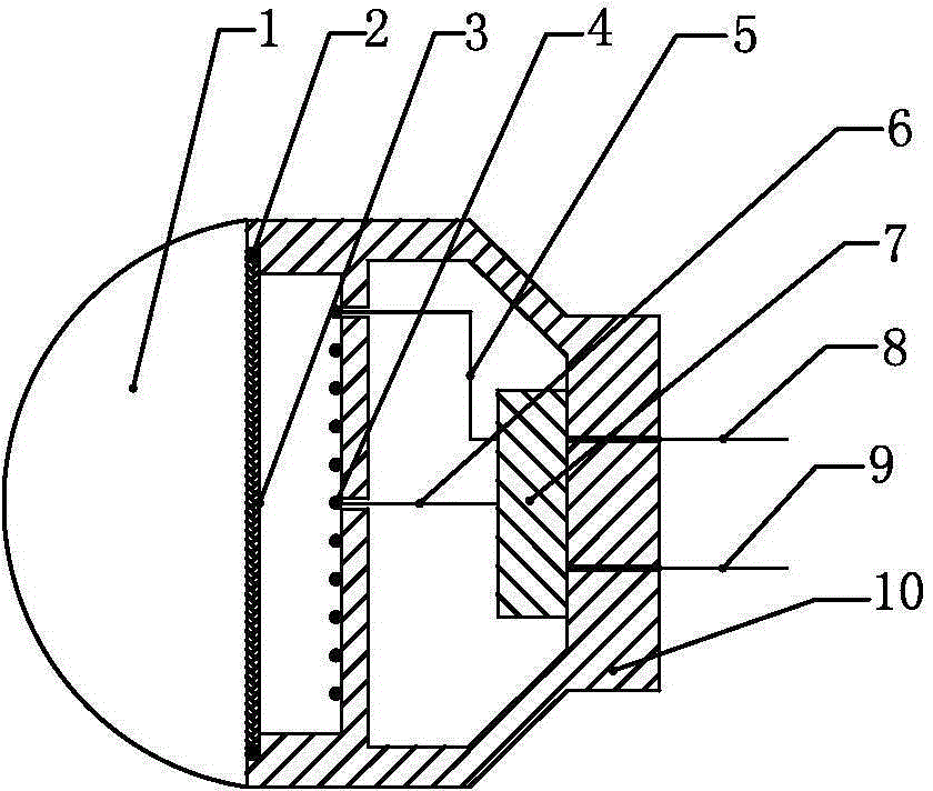
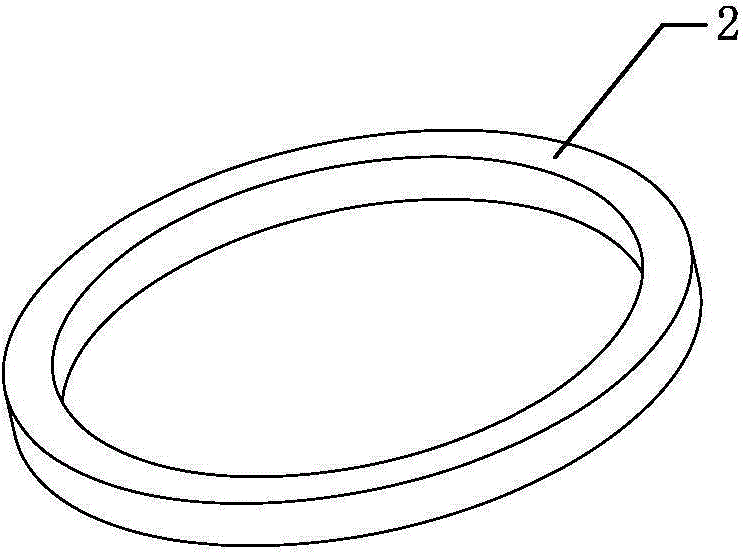
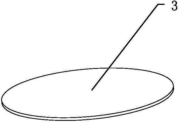
[0024] like figure 1 As shown, the present embodiment includes a protective cover 1, a permanent magnet ring 2, a giant magnetostrictive film 3, a planar spiral coil 4, a circuit board 7 and a housing 10; the protective cover 1 is on the round mouth of the housing 10, The permanent magnet ring 2, the giant magnetostrictive film 3, the planar spiral coil 4, and the circuit board 7 are packaged and fixed in the housing 10, and the giant magnetostrictive film 3 is pasted on the surface of the round mouth of the permanent magnet ring 2; The permanent magnet ring 2, the giant magnetostrictive film 3 and the planar helical coil 4 are parallel and the central axis coincides; the circuit board 7 is designed with a bridge circuit 70; the planar helical coil 4 is connected to the input end of the bridge circuit 70 through a wire; When there is a sound signal, the sound wave will cause the giant magnetostrictive film 3 to deform, and the deformation will change the magnetic permeability ...


PUM


Abstract

The invention discloses a super-magnetostrictive thin film type sound separator. The super-magnetostrictive thin film type sound separator comprises a protecting cover, a permanent magnetic circle ring, a super-magnetostrictive thin film, a plane spiral coil, a circuit board, a first pin, a second pin and a housing; the super-magnetostrictive thin film is manufactured from a super-magnetostrictive material; an electric bridge circuit is arranged on the circuit board; an input contact in the electric bridge circuit is connected with an electrode of the plane spiral coil through a conductor; two output contacts in the electric bridge circuit are respectively connected with the first pin and the second pin; sound wave passes through the protecting cover to cause deformation of the super-magnetostrictive thin film, and the magnetic conductivity is changed, so that the initial inductive value of the plane spiral coil is changed, voltage difference occurs between the first pin and the second pin, and as a result, a sound signal is converted into an electric signal; the problem that the flexibility, stability and accuracy of the current sound sensor cannot be effectively improved can be solved.

Description

technical field [0001] The invention relates to electrical communication techniques in Classification H04, and in particular to sound sensors. Background technique [0002] An acoustic sensor is an energy conversion tool that converts an acoustic signal into an electrical signal. At present, there are many types of sound sensors, which can be divided into electric, capacitive, piezoelectric, electromagnetic, etc. according to the principle of energy conversion. Most of the working principles are that the sound passes through the air to vibrate the diaphragm in the sound sensor to form a weak current signal; or change its capacitance to form a current impedance to generate a corresponding electrical signal. [0003] With the rapid development of modern science and technology, people's awareness of the safety of life and property is getting higher and higher. Analyzing the causes of traffic accidents is one of the effective ways to improve their safety and avoid such accident...

Claims


Application Information

Patent Timeline
IPC IPC(8): H04R15/00
Inventor 王传礼喻曹丰邓海顺何涛
Owner ANHUI UNIV OF SCI & TECH
Learn More