

Object dropping impact mitigation device
A falling and easing technology, applied in the directions of transportation and packaging, loading/unloading, electrical components, etc., can solve the problems of long conveying path, time-consuming, large-scale installation, etc., to reduce impact force, reduce kinetic energy, and simple structure. Effect
- Summary
- Abstract
- Description
- Claims
- Application Information
AI Technical Summary
Problems solved by technology
Method used
Image

Examples
no. 1 Embodiment -
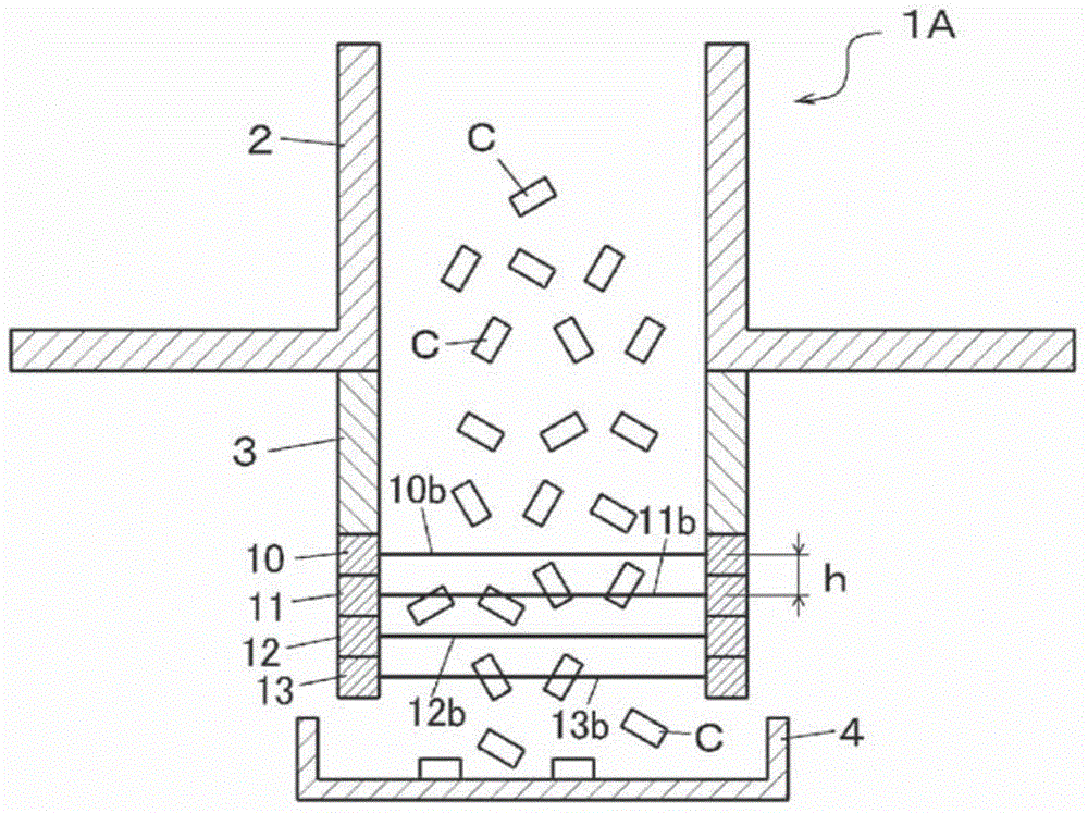
[0050] Figure 1 ~ Figure 4 The first embodiment of the drop impact mitigating device of the present invention is shown. This device 1A alleviates the impact of falling on a chip component (object) C such as a rectangular parallelepiped multilayer ceramic capacitor with a size of 0.5×0.5×1.0 mm, for example. Furthermore, figure 1 It is illustrated for easy understanding, and the dimensional relationship between the chip component C and each member is different from the actual one.
[0051] This impact mitigation device 1 is obtained by fixing the multilayer filters 10 , 11 , 12 , and 13 in a stacked state. Here, although a structure in which four layers of filters are stacked is shown, the number of layers is arbitrary as long as it is two or more layers. This device 1A is fixed to the lower part of the drop tube 2 via the guide tube 3 . A plurality of chip components C are continuously dropped through the drop cylinder 2 .
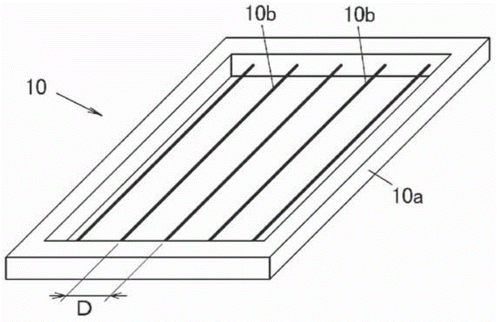
[0052] The filter 10 constituting the device ...
no. 2 Embodiment -
[0060] Figure 5 The second embodiment of the drop impact mitigating device of the present invention is shown. In the first embodiment, an example was shown in which multiple layers of filters 10 to 13 having the same line spacing D are stacked, but in this embodiment, the line spacing of the lower layer filter is narrower than that of the upper layer filter. In other words, the line spacing of each layer of the filter is set so that the upper layer becomes sparser and the lower layer becomes denser.
[0061] For example, if the line interval of the filter 10 of the uppermost layer is set as D1, the line interval of the filter 11 of the second layer is set as D2, the line interval of the filter 12 of the third layer is set as D3, and the line interval of the filter 12 of the third layer is set as D3, The line spacing of the filter 13 of the layer is set to D4, then becomes
[0062] D1>D2>D3>D4. Furthermore, it is preferable that even the smallest interval D4 is larger than ...
no. 3 Embodiment -
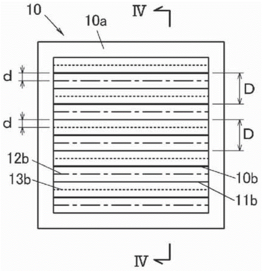
[0068] Image 6 , Figure 7 A third embodiment of the drop impact mitigation device of the present invention is shown. In this example, the filters 10 , 11 , 12 , and 13 are stacked so that the positions of the lines of the filters adjacent up and down are non-parallel. exist Image 6 Among them, the line 10b of the uppermost layer is represented by a thick line, the line 11b of the second layer is represented by a thin line, the line 12b of the third layer is represented by a one-dot chain line, and the line 13b of the fourth layer is represented by a dotted line. Here, although the direction of the line of the filter on the upper side is orthogonal to the direction of the line of the filter on the lower side was shown, it does not have to be orthogonal. The interval D between the lines provided in one filter is larger than the maximum size of the chip component C as in the first embodiment. Furthermore, in a projected view obtained by vertically projecting the multilayer...
PUM
 Abstract
Description
Claims
Application Information