Biomolecular detection test strip design
A biological sample, electronic sensor technology, applied in the field of test strip design for biomolecule detection, can solve the problems of non-portability and time-consuming
- Summary
- Abstract
- Description
- Claims
- Application Information
AI Technical Summary
Problems solved by technology
Method used
Image
Examples
Embodiment approach 1- 1
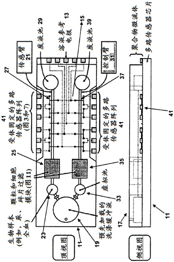
[0091] Embodiment 1 - A device comprising: (a) a substrate comprising a plurality of electrodes; (b) a plurality of electronic sensors integrated or assembled on said substrate and connected to said electrodes; and (c) A microfluidic component is disposed on the substrate and adapted to be in fluid communication with the electronic sensor.
[0092] Embodiment 2 - The device of Embodiment 1, wherein said microfluidic assembly comprises at least one buffer reservoir and at least one sensing arm connected to said buffer reservoir, wherein said sensing arm comprises a sample reservoir, A sample filtration module and a sample sensing region adapted to be in fluid communication with at least one of the electronic sensors.
[0093] Embodiment 3 - The device of Embodiment 2, wherein said buffer reservoir comprises at least one buffer.
[0094] Embodiment 4 - The device of any one of Embodiments 2 to 3, wherein said sensing arm further comprises a reference cell upstream of said sampl...
Embodiment approach 12- 1
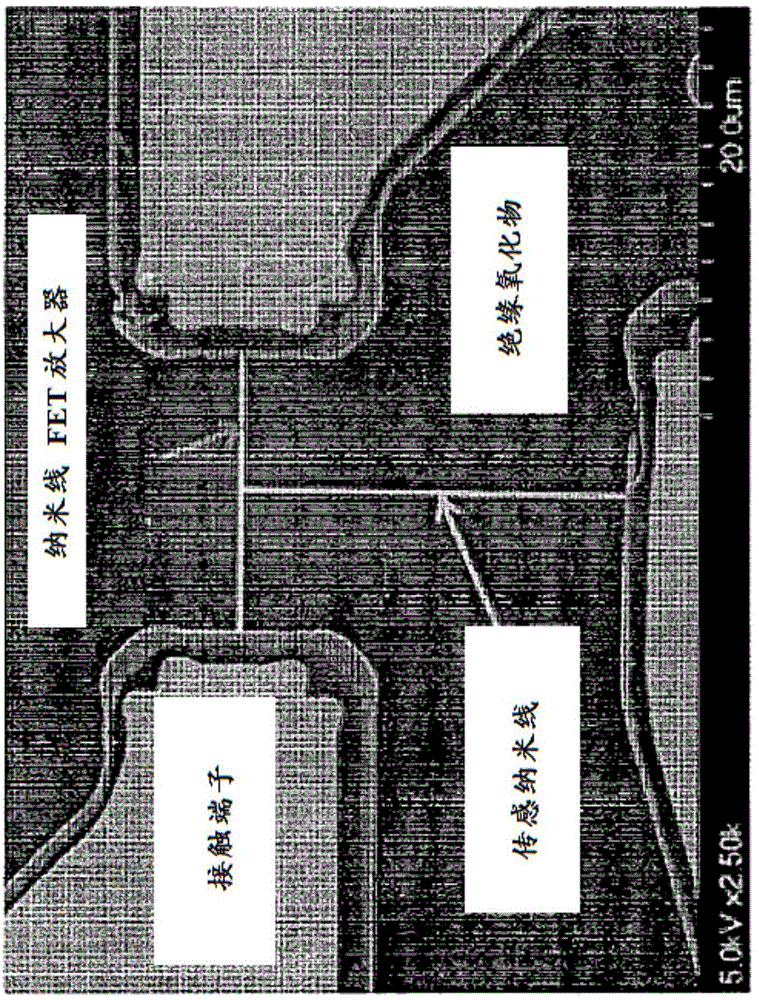
[0102]Embodiment 12 - A device comprising: (a) a substrate comprising a plurality of electrodes; (b) a plurality of nanowire field effect transistor (nwFET) sensors embedded or disposed on the substrate and connected to the wherein each of the nwFET sensors comprises a T-shaped structure comprising a lateral nanowire FET amplifier and a vertical sensing nanowire connected to the lateral nanowire FET amplifier, wherein the sensor a sensing nanowire and optionally a node connecting said sensing nanowire to a nanowire FET amplifier comprising a receptor affixed thereon, and wherein said nanowire FET amplifier is passivated; and (c) a microfluidic assembly, which disposed on the substrate and adapted to be in fluid communication with the nwFET sensor, the microfluidic assembly comprising: (i) at least one buffer reservoir comprising at least one buffer; (ii) at least one sensing arm, connected to said at least one buffer reservoir, said sensing arm comprising a sample reservoir, a...
Embodiment approach 13- 1
[0103] Embodiment 13 - A method of detecting the presence of a biomarker comprising: (A) providing a device comprising: (a) a substrate comprising a plurality of electrodes; (b) a plurality of electronic sensors in said integrated or assembled on a substrate and connected to said electrodes; and (c) a microfluidic assembly disposed on said substrate and adapted to be in fluid communication with said electronic sensor; and (B) introducing a biological sample into said microfluidic In an assembly, wherein the microfluidic assembly directs the flow of the biological sample to contact at least one of the electronic sensors, and wherein the presence of the biomarker causes at least one of the electronic sensors Signal changes.
[0104] Embodiment 14 - The method of Embodiment 13, wherein said microfluidic assembly comprises at least one sensing arm connected to at least one buffer well, said buffer well comprising at least one buffer; wherein said sensing arm a sensing arm compris...
PUM
| Property | Measurement | Unit |
|---|---|---|
| width | aaaaa | aaaaa |
| width | aaaaa | aaaaa |
Abstract
Description
Claims
Application Information
 - R&D
- Intellectual Property
- Life Sciences
- Materials
- Tech Scout
- Unparalleled Data Quality
- Higher Quality Content
- 60% Fewer Hallucinations
Browse by: Latest US Patents, China's latest patents, Technical Efficacy Thesaurus, Application Domain, Technology Topic, Popular Technical Reports.
© 2025 PatSnap. All rights reserved.Legal|Privacy policy|Modern Slavery Act Transparency Statement|Sitemap|About US| Contact US: help@patsnap.com


