Wall allowing heat transfer coefficient to be automatically adjusted

A heat transfer coefficient and automatic adjustment technology, which is applied to walls, building components, buildings, etc., can solve the problems of increasing heat and no automatic adjustment of heat transfer coefficient, etc., and achieves the effect of easy realization, broad market and practical prospects, and simple structure

Inactive Publication Date: 2015-06-17
NORTH CHINA UNIVERSITY OF TECHNOLOGY
View PDF5 Cites 19 Cited by
  • Summary
  • Abstract
  • Description
  • Claims
  • Application Information

AI Technical Summary

Problems solved by technology

If the heat transfer coefficient is designed too large, although the heat conducted from the indoor air to the outside through the wall at night is increased, the heat conducted to the room through the wall during the day is also increased.
Therefore, the wall with a fixed heat transfer coefficie...

Method used


Image

  • Wall allowing heat transfer coefficient to be automatically adjusted
  • Wall allowing heat transfer coefficient to be automatically adjusted
  • Wall allowing heat transfer coefficient to be automatically adjusted

Examples


Embodiment 1

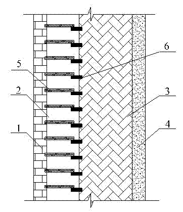
[0030] as attached figure 1 As shown, the wall body with automatic adjustment of heat transfer coefficient includes a surface layer 1, a thermal resistance layer 2, a load-bearing layer 3 and a surface layer 4, each layer is stacked in sequence, and a The heat variable resistance layer 2 is also provided with a surface layer 4 on the inner surface of the load-bearing layer 3 . The variable thermal resistance layer 2 includes several bimetallic sheets 5 and several thermally conductive substrates 6, each bimetallic sheet 5 and a corresponding thermally conductive substrate 6 constitute a conductive thermal bridge between the surface layer 1 and the load-bearing layer 3, along the wall A number of parallel thermal conduction bridges are established between the surface layer 1 and the load-bearing layer 3 in the height direction of the body. For each conduction heat bridge, one end of the heat-conducting matrix 6 is fixed on the surface of the load-bearing layer facing the surfa...

Embodiment 2

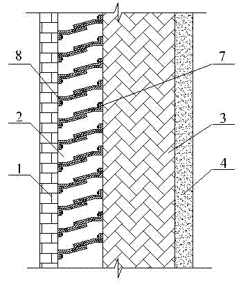
[0032] The main difference between Example 2 and Example 1 lies in the variable thermal resistance layer. In Example 2, the thermally conductive substrate in Example 1 is replaced by a bimetallic sheet. Other structural settings are the same, as shown in the attached figure 2 As shown, the variable thermal resistance layer 2 includes several bimetallic strips 7 and several bimetallic strips 8, and a corresponding group of bimetallic strips constitutes a conduction heat bridge between the surface layer 1 and the load-bearing layer 3, along the wall height direction Several groups of conduction heat bridges are established between the surface layer 1 and the load-bearing layer 3 . For each conduction heat bridge, one end of the bimetallic strip 7 is fixed on the surface of the load-bearing layer, one end of the bimetallic strip 8 is fixed on the surface of the surface layer 1, and the bimetallic strip 7 is fixed on the surface of the surface layer. The other end is freely lappe...

Embodiment 3

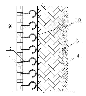
[0034] The main difference between embodiment 3 and embodiment 1 is that in embodiment 3, a round-headed bimetal sheet and a heat conduction plate are used in the variable thermal resistance layer, and other structural settings are the same, as shown in the attached image 3 As shown, the variable thermal resistance layer arranged between the surface layer 1 and the load-bearing layer 3 includes several round-headed bimetallic sheets 9 and a heat conducting plate 10, one end of the round-headed bimetallic sheet 9 is linear, and the other end Bent into a circle, the straight end of the round head bimetal 9 is fixed on the surface of the surface layer 1 facing the load-bearing layer, and the heat conducting plate 10 is arranged along the entire surface of the load-bearing layer facing the surface layer 1, and is fixed on the surface of the load-bearing layer. on the entire surface. In a normal state, the circular curved end of the round-headed bimetal 9 abuts against the surface...


PUM


Abstract

The invention provides a wall allowing a heat transfer coefficient to be automatically adjusted. The wall comprises a surface layer, a variable heat resistance layer and a load bearing layer. The variable heat resistance layer is arranged between the surface layer and the load bearing layer and comprises double metal sheets. In a cold state, the double metal sheets directly or indirectly make contact with the surface layer and the load bearing layer to build a conduction heat bridge between the surface layer and the load bearing layer, and the heat transfer coefficient of the wall is increased. In a hot state, the double metal sheets bend, deform and separate from the surface layer and/or the load bearing layer, so that the conduction heat bridge between the surface layer and the load bearing layer is broken, and the heat transfer coefficient of the wall is decreased. Through the wall allowing the heat transfer coefficient to be automatically adjusted, the quantity of heat conducted from outdoor space into indoor space in daytime can be reduced, an outdoor cold source can also be sufficiently used for cooling indoor air at night, and air-conditioning energy consumption is reduced.

Description

technical field [0001] The invention relates to the technical field of environmental protection walls, in particular to a wall with automatic adjustment of heat transfer coefficient. Background technique [0002] The exterior wall of the building is the interface between the interior space and the exterior space of the building. The heat exchange between the interior space of the building and the exterior space is realized through the intermediary of the wall. Therefore, the heat transfer coefficient of the wall has a great influence on the building energy consumption. The greater the heat transfer coefficient, the more heat is conducted through the wall. The lower the heat transfer coefficient, the less heat is conducted through the wall. In summer, when the outdoor temperature is too high during the day, in order to reduce the energy consumption of the air conditioner, the heat transferred into the room through the wall should be reduced, so the smaller the heat transfe...

Claims


Application Information

Patent Timeline
IPC IPC(8): E04B2/00E04B1/74
Inventor 李志永赵玉清高建岭白玉星张帆张立洋
Owner NORTH CHINA UNIVERSITY OF TECHNOLOGY
Why Eureka
Try Eureka