Eureka AIR delivers breakthrough ideas for toughest innovation challenges, trusted by R&D personnel around the world.

Compression Method of Echo Energy Dynamic Range of LiDAR System

A technology of echo energy and dynamic range, which is applied in the field of compression of the dynamic range of echo energy of the laser radar system, can solve problems such as no clear and quantitative conclusions are given, and achieve the effect of compressing the dynamic range, strong stability, and good effect

Inactive Publication Date: 2017-05-10
WUHAN UNIV
View PDF5 Cites 2 Cited by
  • Summary
  • Abstract
  • Description
  • Claims
  • Application Information

AI Technical Summary

Problems solved by technology

For the key method of compressing the dynamic range of laser echo energy, the above research did not give a clear and quantitative conclusion

Method used


Image

  • Compression Method of Echo Energy Dynamic Range of LiDAR System
  • Compression Method of Echo Energy Dynamic Range of LiDAR System
  • Compression Method of Echo Energy Dynamic Range of LiDAR System

Examples


specific Embodiment

[0073] The method proposed by the present invention is illustrated by Examples 1 and 2, and the optical parameters of Examples 1 and 2 are shown in Table 1.

[0074]

example 1

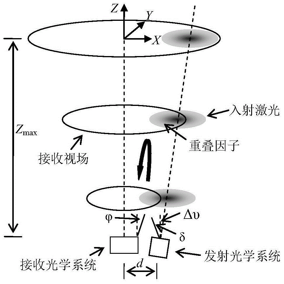
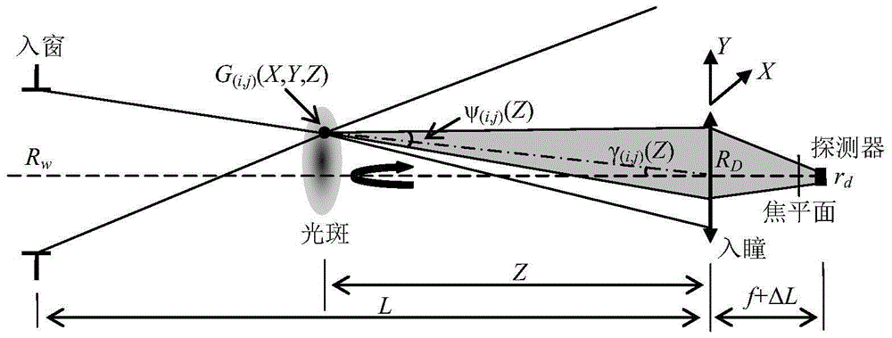
[0076] Maximum detection distance Z in example 1 max is 150m, and the critical value of the negative angle Δυ between the emitting optical axis and the receiving optical axis is calculated by formula (12) to be 1.35mrad; the focusing amount of the detector is calculated by formula (13) to be 0.08mm to 0.11mm, Its corresponding window position is between 90m and 120m.

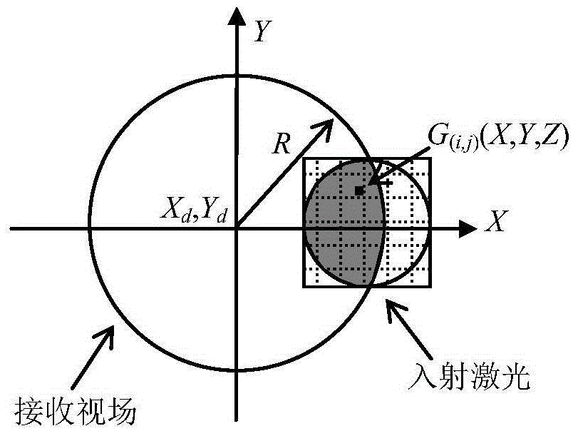
[0077] Figure 5 It is the relationship diagram between the overlap factor and the detection distance when the negative angle between the two axes changes in Example 1, Figure 6 It is the relationship diagram between the laser echo energy and the detection distance when the negative angle between the two axes changes in Example 1. From Figure 5 and Figure 6 It can be seen from the comparison that in the detection area from 1m to 150m, when the negative angle Δυ gradually increases from 0° to 1.6mrad, the rate of increase of the overlap factor O(Z) decreases significantly with the increase of the detection...

example 2

[0079] Maximum detection distance Z in Example 2 max is 500m, the critical value of the negative angle Δυ between the emission optical axis and the receiving optical axis is calculated by the formula (12) to be 0.75mrad; the focusing amount of the detector is calculated by the formula (13) to be 0.1mm to 0.13mm, Its corresponding window position is between 300m and 400m.

[0080] Figure 8 It is the relationship diagram between the overlap factor and the detection distance when the negative angle between the two axes changes in Example 2, Figure 9 It is the relationship diagram between the laser echo energy and the detection distance when the negative angle between the two axes changes in Example 2. From Figure 8 and Figure 9 It can be seen from the comparison that in the detection area from 5m to 500m, when the negative angle Δυ gradually increases from 0° to 0.75mrad, the rate of increase of the overlap factor O(Z) decreases significantly with the increase of the dete...


PUM


Abstract

The invention relates to a compression method for a dynamic range of echo energy of a laser radar system. The compression method is particularly suitable for a two-shaft structure. A certain negative included angle is formed between a light emission shaft and a light receiving shaft, so that the rising rate, which is increased with the detection distance, of an overlapping factor is reduced, and the dynamic range of the laser echo energy can be compressed favorably; furthermore, a detector is arranged at a position spaced from a focal plane of an optical system at a distance so as to obtain an optimal laser echo energy response. Due to an experimental formula and a conclusion which are provided by theoretical analysis and value calculation, the compression method has a guiding significance for the whole design and the performance estimation of the laser radar system.

Description

technical field [0001] The invention relates to the technical field of laser radar, in particular to a method for compressing the dynamic range of echo energy of a laser radar system. Background technique [0002] Lidar is a remote sensing device with extremely high temporal and spatial resolution and measurement accuracy, and is widely used in unmanned navigation vehicles, 3D urban modeling, terrain surveying, atmospheric detection and other technical fields. In order to increase the ranging range of the laser radar system, it is necessary to compress the dynamic range of the laser echo energy in the pre-detection area. At present, in high-speed measurement, Reigl, Velodyne, Optech, Beike Tianhui and other internationally renowned lidar manufacturers use circuit control to compress the dynamic range of laser echo energy, which has the disadvantages of insufficient stability, strong crosstalk, high delay, and poor technology. There are disadvantages such as difficulty, and ...

Claims


Application Information

Patent Timeline
Patent Type & Authority Patents(China)
IPC IPC(8): G01S7/493G01S17/88
CPCG01S7/481
Inventor 李松史光远黄科李子乐杨晋陵
Owner WUHAN UNIV
Why Eureka
Eureka Blog
Learn More