
Auxiliary face compensation method for large beam-forming double-reflection-face antenna based on electromechanical coupling

A dual-reflector, electromechanical coupling technology, applied in electrical digital data processing, special data processing applications, instruments, etc., can solve problems such as the decline of electrical performance of large-scale shaped dual-reflector antennas

Inactive Publication Date: 2015-06-17
XIDIAN UNIV
View PDF4 Cites 15 Cited by
  • Summary
  • Abstract
  • Description
  • Claims
  • Application Information

AI Technical Summary

Problems solved by technology

[0005] Aiming at the deficiencies of the previous compensation methods, the present invention provides a compensation method for the subsurface of a large shaped double reflector antenna based on electromechanical coupling. This method mainly solves the electrical performance of the large shaped double reflector antenna caused by thermal deformation. To solve the drop problem, improve the electrical performance of the antenna by adjusting the position and orientation of the secondary surface

Method used


Image

  • Auxiliary face compensation method for large beam-forming double-reflection-face antenna based on electromechanical coupling
  • Auxiliary face compensation method for large beam-forming double-reflection-face antenna based on electromechanical coupling
  • Auxiliary face compensation method for large beam-forming double-reflection-face antenna based on electromechanical coupling

Examples


Embodiment Construction

[0071] The present invention will be further described below in conjunction with the accompanying drawings and embodiments.

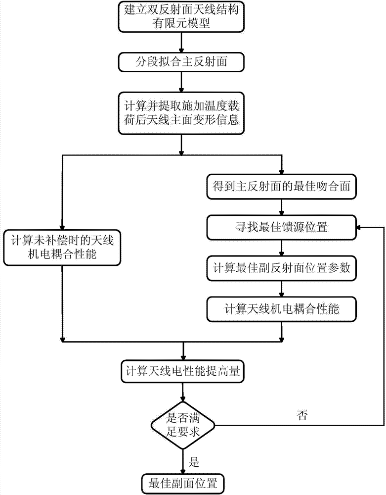
[0072] refer to figure 1 , a subsurface compensation method for a large shaped double-reflector antenna based on electromechanical coupling, the specific steps are as follows:

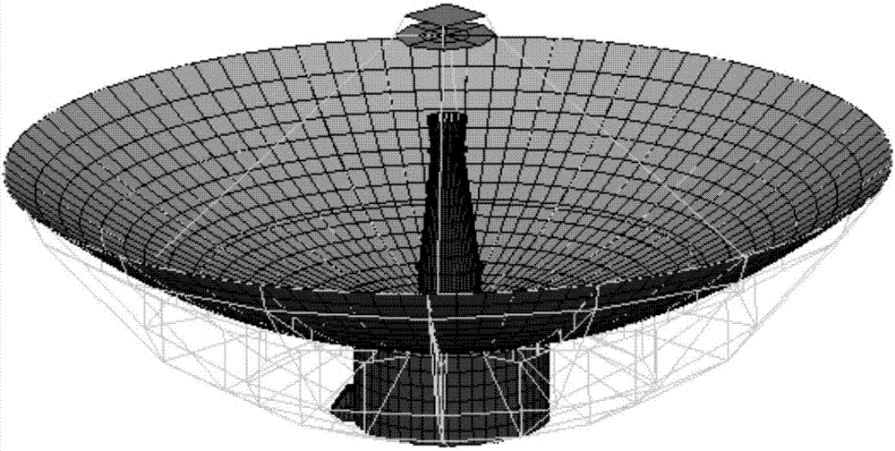
[0073] Step 1. Establish the finite element model of the undeformed shaped double reflector antenna, extract the node coordinates and element information of the undeformed secondary reflector and the node coordinates and element information of the main reflector

[0074] According to the structural parameters, operating frequency and material properties of the large shaped double reflector antenna, the finite element model of the undeformed shaped double reflector antenna is established in ANSYS software. The structural parameters include the main and secondary reflector apertures. Material properties include density, thermal conductivity, specific heat, Poisson's ratio, modulu...


PUM


Abstract

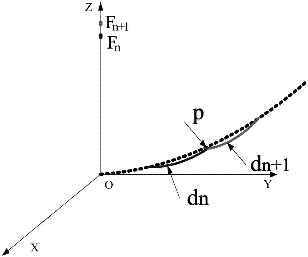
The invention discloses an auxiliary face compensation method for a large beam-forming double-reflection-face antenna based on electromechanical coupling. The method includes the steps that firstly, an antenna finite element model is established; secondly, a piecewise fitting face of an antenna beam-forming main reflection face is acquired; thirdly, according to loaded temperature loads, node coordinates of the deformed antenna main reflection face are calculated; fourthly, the electrical property of the deformed antenna is calculated; fifthly, the optical matching face of the deformed antenna main reflection face is acquired; sixthly, a focal point is taken from a focal axis corresponding to the optimal matching face, and the position of the focal point corresponding to the optical matching face serves as an optimal feed source position by calculating the electrical property of the antenna; seventhly, the auxiliary reflection face position adjusting amount for compensating for the electrical property of the antenna is calculated, and the electrical property of the antenna after compensation is calculated; eighthly, whether the increase amount before and after the auxiliary face position is adjusted meets requirements or not is judged, and the auxiliary face position is adjusted till the requirements are met. The reflection face antenna quantitative analysis and modeling processes are simplified, the calculation process is improved, and the weight and the manufacturing cost of the antenna are reduced.

Description

technical field [0001] The invention belongs to the technical field of antennas, and specifically relates to a secondary surface compensation method of a large-scale shaped double-reflector antenna based on electromechanical coupling, which is used to adjust the position of the secondary reflector of the shaped double-reflector antenna to optimize the electrical performance of the antenna . Background technique [0002] Large antennas play an extremely important role in major projects such as deep space exploration and missile defense systems. As the boundary condition of electromagnetic wave propagation, the reflective panel directly affects the electrical performance of the antenna. Under the action of gravity load, temperature load and wind load, etc., the antenna will undergo structural deformation, which will cause the reflective surface to deviate from the shape required by the electrical design, thereby seriously affecting the electrical performance of the antenna. ...

Claims


Application Information

Patent Timeline
IPC IPC(8): G06F17/50
Inventor 王从思杨崇金彭雪林王伟王艳陈光达朱敏波张逸群黄进刘鑫肖岚邓昌炽
Owner XIDIAN UNIV
Learn More