Stable vehicle driving zone determining method

A technology for vehicle driving and determining methods, applied to vehicle components, vehicle condition input parameters, instruments, etc., can solve the problem of not systematically describing phase plane stability regions and non-stable regions, and unable to analyze, control and evaluate vehicle stability In order to achieve the effects of real-time performance, reliable accuracy, simple and practical modeling process, and resource and cost saving

Active Publication Date: 2016-09-21
JILIN UNIV
View PDF5 Cites 16 Cited by
  • Summary
  • Abstract
  • Description
  • Claims
  • Application Information

AI Technical Summary

Problems solved by technology

However, the current research on the phase plane is very limited, and there is no systematic description of the stability region and the instability region of the phase plane. The versatility is very poor, so it cannot be used to analyze, control and evaluate the vehicle well. The stability characteristics of

Method used


Image

  • Stable vehicle driving zone determining method
  • Stable vehicle driving zone determining method
  • Stable vehicle driving zone determining method

Examples


Embodiment Construction

[0028] Below in conjunction with the accompanying drawings, the technical solution proposed by the invention is further elaborated and illustrated.

[0029] The invention provides a method for determining a vehicle stability region, the method comprising the following steps:

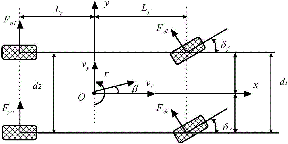
[0030] 1. Combining the vehicle lateral motion mechanism and the Unitire unified tire model to establish a complete vehicle lateral dynamics model

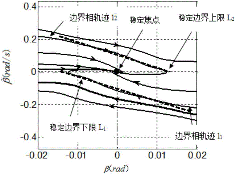
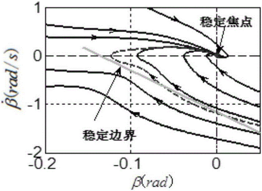
[0031] In order to obtain the center-of-mass angular velocity-slip angle phase diagram of the vehicle, the present invention establishes a complete vehicle dynamics model for the yaw motion and lateral motion of the vehicle, and first makes the following assumptions:

[0032] Regardless of the influence of the steering system of the vehicle, the front wheel rotation angle δ f as input to the system;

[0033] Neglecting the effect of the suspension, it is considered that the displacement of the car along the z-axis, the roll angle around the x-axis and ...


PUM


Abstract

The invention discloses a stable vehicle driving zone determining method. The stable vehicle driving zone determining method mainly comprises the following steps that step one, a complete vehicle side dynamical model is established; step one, mass center side slip angle speed-mass center side slip angle phase trajectory curve family of a vehicle is drawn; step three, a stable boundary phase trajectory is determined; step four, a stable boundary is fit in the form of a straight line; step five, a three-dimensional map of stable boundary slope and intercept about the vehicle speed and a road adhesion coefficient is made. The stable vehicle driving zone determining method quantitatively represent a stable vehicle driving zone, is simple modeling and has a certain real-timeliness and effectiveness.

Description

technical field [0001] The invention relates to a method for determining a driving stability region of a vehicle, in particular to a method for determining a driving stability region of a vehicle by processing a three-dimensional map of a center of mass sideslip angle phase plane stability boundary. Background technique [0002] The phase plane is a graphic solution method for the motion trajectory of a nonlinear system. It is not necessary to solve the nonlinear equation specifically. By drawing the motion trajectory of the system on the phase plane, the relationship between related variables can be observed intuitively and accurately, so as to determine The kinematic form of the solution of the system under different initial conditions. For a highly nonlinear system like a vehicle, phase plane analysis is a comprehensive, intuitive and effective method to characterize its characteristics. At present, there are mainly two types of phase planes for vehicle stability, one is...

Claims


Application Information

Patent Timeline
Patent Type & Authority Applications(China)
IPC IPC(8): B60W40/10B60W40/103G06F17/50
CPCB60W40/10B60W40/103B60W2530/20B60W2720/20G06F30/20Y02T90/00
Inventor 郭洪艳宋林桓刘风
Owner JILIN UNIV
Why Eureka
Try Eureka