Rapid solar-thermal conversion of biomass to syngas

a solar-thermal conversion and biomass technology, applied in the field of solar biomass gasification and pyrolysis, can solve problems such as major concerns in loss, achieve the effects of accelerating reaction kinetics, increasing reaction rate, and widening the range of thermodynamic regimes availabl

Active Publication Date: 2008-04-17
UNIV OF COLORADO THE REGENTS OF
View PDF18 Cites 139 Cited by
  • Summary
  • Abstract
  • Description
  • Claims
  • Application Information

AI Technical Summary

Benefits of technology

[0009] The invention provides processes that perform biomass gasification or pyrolysis for production of hydrogen, synthesis gas, liquid fuels, or other hydrocarbon based chemicals. The methods of the invention use solar thermal energy as the energy source for the biomass pyrolysis or gasification. This allows operation at temperatures above 950° C., speeding up reaction kinetics and shifting thermodynamics to various reaction end products, thus, bypassing the formation of tars and other liquids that have a tendency to cause plugging or increased pressure drop in gas / solid filtration devices downstream of the reactor and which are undesired side products. The increase in reaction rate, the use of a renewable energy resource, the avoidance of tars, and the wider range of available thermodynamic regimes give great advantage to one who would utilize solar thermal energy. Usage of solar thermal energy can reduce the overall amount of biomass required to produce the product chemicals, allows for a greater range of product control, does not rely on fossil fuel usage, and takes advantage of a freely available resource (solar energy).

Problems solved by technology

Temperatures even higher than this are achievable, but in those regimes materials and reradiation loss issues become major concerns.

Method used


Image

  • Rapid solar-thermal conversion of biomass to syngas
  • Rapid solar-thermal conversion of biomass to syngas
  • Rapid solar-thermal conversion of biomass to syngas

Examples


example 1

Cellulose Gasification in an Electrically Heated Aerosol Transport Tube Reactor

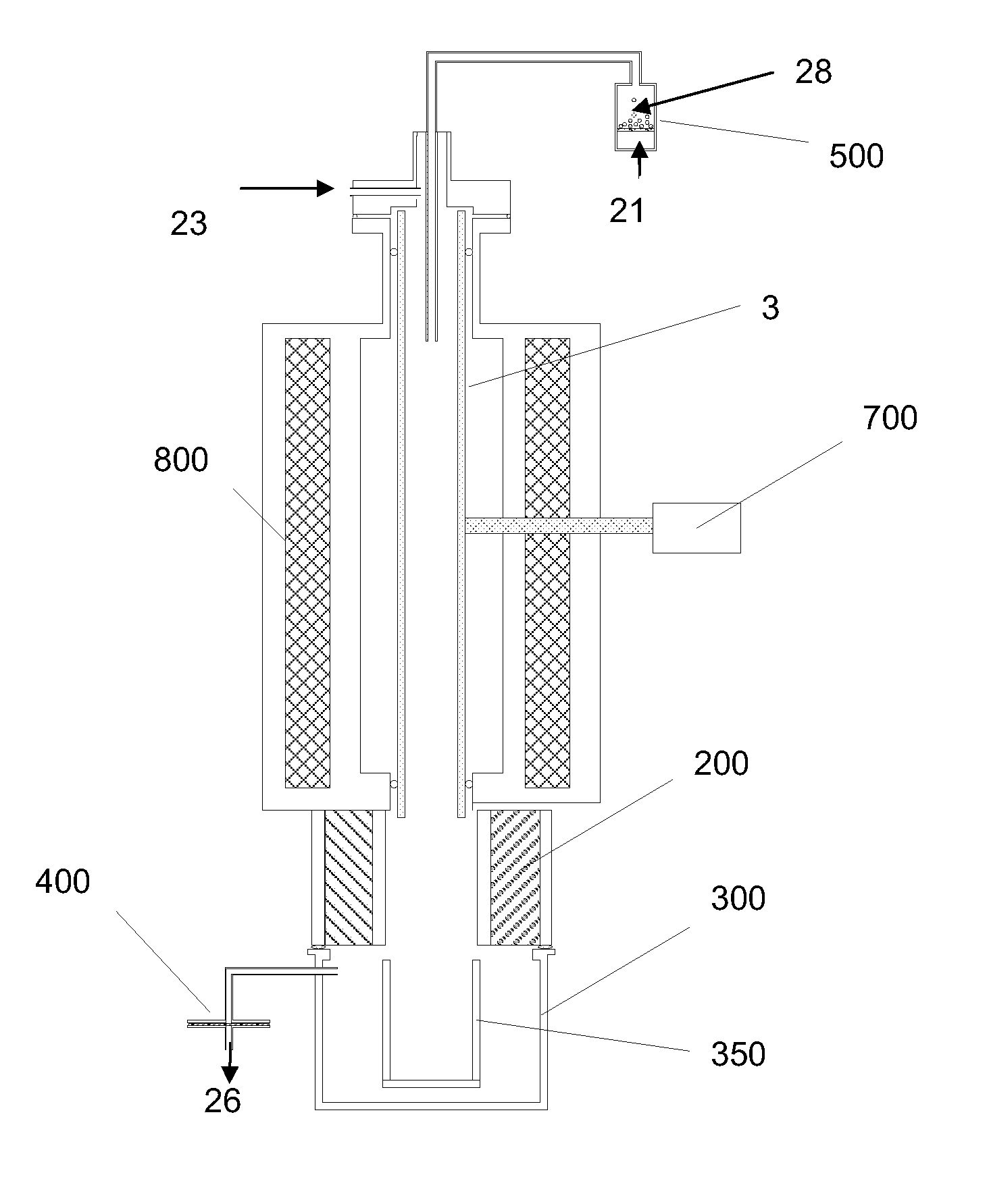
[0106] Cellulose was combined with water vapor in an electric tube furnace at temperatures between 1200 K and 1450 K. The cellulose was composed of fine particles (Sigma-Aldrich #310697, 20 μm) with a monomer unit shown in FIG. 3. The reactor apparatus is shown in FIG. 4. The reactor consisted of a 99.8% Alumina tube (3) (McDanel Technical Ceramics), 3.635″ in internal diameter by 45″ in length. This tube was heated indirectly using a surrounding electrically heated graphite resistance element (800). The interior of the Al2O3 tube was sealed from the outer graphite element and purged with argon gas to eliminate oxygen. Particles of cellulose were placed in a fluidized bed feeder (500); fluidization gas (21) (argon) entrained the particles, carrying them into the hot reactor, where they were combined with water vapor (23). The water flowrate was controlled by a syringe pump, and the water was introduced i...

example 2

Lignin Gasification in an Electrically Heated Aerosol Transport Tube Reactor

[0112] Lignin was combined with water vapor in an electric tube furnace at 1450 K. The lignin was composed of fine particles (Sigma-Aldrich #371017, 20 μm) with a monomer unit shown in FIG. 6. The reactor was the same as in Example 1. The interior of the Al2O3 tube was sealed from the outer graphite element and purged with argon gas to eliminate oxygen. Particles of lignin were placed in a fluidized bed feeder; fluidization gas (argon) entrained the particles, carrying them into the hot reactor, where they were combined with water vapor. The water flowrate was controlled by a syringe pump, and the water was introduced into the hot reactor environment through a capillary tube.

[0113] After leaving the heated portion of the reactor, the reaction products were passed through a gravity collection vessel and an HEPA filter (200 nm pore size). Large particles would be collected in the gravity vessel, with smaller...

example 3

Cellulose and Lignin Pyrolysis in an Electrically Heated Aerosol Transport Tube Reactor

[0116] Cellulose and lignin were pyrolyzed in an electric tube furnace at temperatures between 1200 K and 1450 K. Each material was fed in separate experiments. The cellulose was composed of fine particles (Sigma-Aldrich #310697, 20 μm) and the lignin was also composed of fine particles (Sigma-Aldrich #371017) The reactor apparatus is similar to that in Example 1. The interior of the Al2O3 tube was sealed from the outer graphite element and purged with argon gas to eliminate oxygen. Particles of cellulose or lignin were placed in a fluidized bed feeder; fluidization gas (argon) entrained the particles, carrying them into the hot reactor, where they joined by sweep argon gas to control residence time.

[0117] After leaving the heated portion of the reactor, the reaction products were passed through a gravity collection vessel and an HEPA filter (200 nm pore size). Large particles would be collected...


PUM

PropertyMeasurementUnit
volume average equivalent spherical particle diameteraaaaaaaaaa
temperatureaaaaaaaaaa

Abstract

Methods for carrying out high temperature reactions such as biomass pyrolysis or gasification using solar energy. The biomass particles are rapidly heated in a solar thermal entrainment reactor. The residence time of the particles in the reactor can be 5 seconds or less. The biomass particles may be directly or indirectly heated depending on the reactor design. Metal oxide particles can be fed into the reactor concurrently with the biomass particles, allowing carbothermic reduction of the metal oxide particles by biomass pyrolysis products. The reduced metal oxide particles can be reacted with steam to produce hydrogen in a subsequent process step.

Description

CROSS-REFERENCE TO RELATED APPLICATIONS [0001] This application claims the benefit of U.S. Provisional Application 60 / 823,872, filed Aug. 29, 2006, which is hereby incorporated by reference to the extent not inconsistent with the disclosure herein.STATEMENT REGARDING FEDERALLY SPONSORED RESEARCH OR DEVELOPMENT [0002] The invention was made with Government support from the National Science Foundation Graduate Research Fellowship program. The United States government may have certain rights in the invention.BACKGROUND OF THE INVENTION [0003] This invention is in the field of solar biomass gasification and pyrolysis [0004] As processes, biomass gasification and pyrolysis have been known for a long time. Several different types of reactors have been used to gasify and / or pyrolize biomass including fixed bed reactors, fluidized bed reactors, and entrained flow reactors. A variety of sources of heat for biomass gasification and pyrolysis processes have been used, including fossil fuels (N...

Claims


Application Information

Patent Timeline
Patent Type & Authority Applications(United States)
IPC IPC(8): C10J3/48C10J3/60
CPCC10B19/00C22B7/001C01B3/586C10J2300/0973F24J2/42C01B2203/0283C22B5/10Y02E60/36C01B3/12C10J2300/1284Y02E50/32C10J2300/1292C10J3/506C01B2203/0445C10J2300/0916Y02E50/14C01B2203/047C22B5/12B01J19/127Y02E10/40C10J2300/0983C01B3/10C10B53/02C10J2300/092C10J3/485Y02P20/145Y02P10/122F24S90/00Y02E50/30Y02E50/10Y02P10/20Y02P20/133
Inventor WEIMER, ALAN W.PERKINS, CHRISTOPHERMEJIC, DRAGANLICHTY, PAUL
Owner UNIV OF COLORADO THE REGENTS OF
Why Eureka
Try Eureka