Method for manufacturing fin field effect transistor (FET)

A fin-type field effect and transistor technology, applied in semiconductor/solid-state device manufacturing, electrical components, circuits, etc., can solve problems such as increased process difficulty, achieve self-alignment, avoid damage, and control etching accuracy.

Inactive Publication Date: 2015-06-17
SHANGHAI HUALI MICROELECTRONICS CORP
View PDF5 Cites 2 Cited by
  • Summary
  • Abstract
  • Description
  • Claims
  • Application Information

AI Technical Summary

Problems solved by technology

However, this method is a huge challenge for the self-alignment requirements during lithography, which will increase the difficulty of the process

Method used


Image

  • Method for manufacturing fin field effect transistor (FET)
  • Method for manufacturing fin field effect transistor (FET)
  • Method for manufacturing fin field effect transistor (FET)

Examples


Embodiment Construction

[0027] The specific embodiment of the present invention will be further described in detail below in conjunction with the accompanying drawings.

[0028] It should be noted that, in the following specific embodiments, when describing the embodiments of the present invention in detail, in order to clearly show the structure of the present invention for the convenience of description, the structures in the drawings are not drawn according to the general scale, and are drawn Partial magnification, deformation and simplification are included, therefore, it should be avoided to be interpreted as a limitation of the present invention.

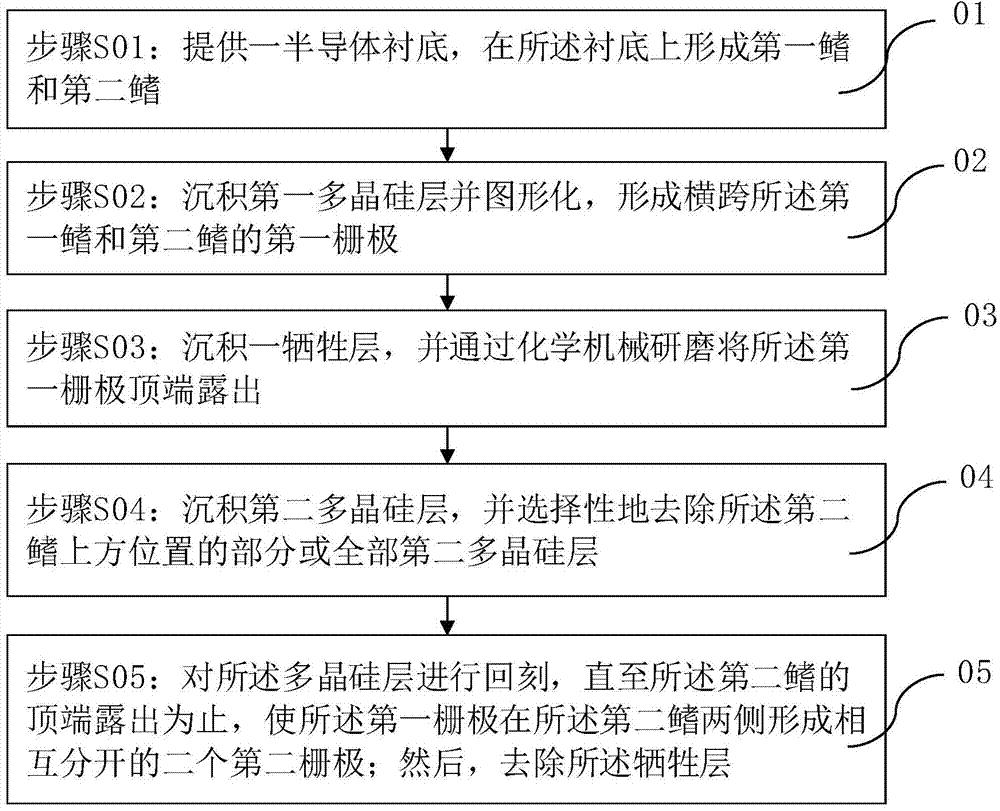
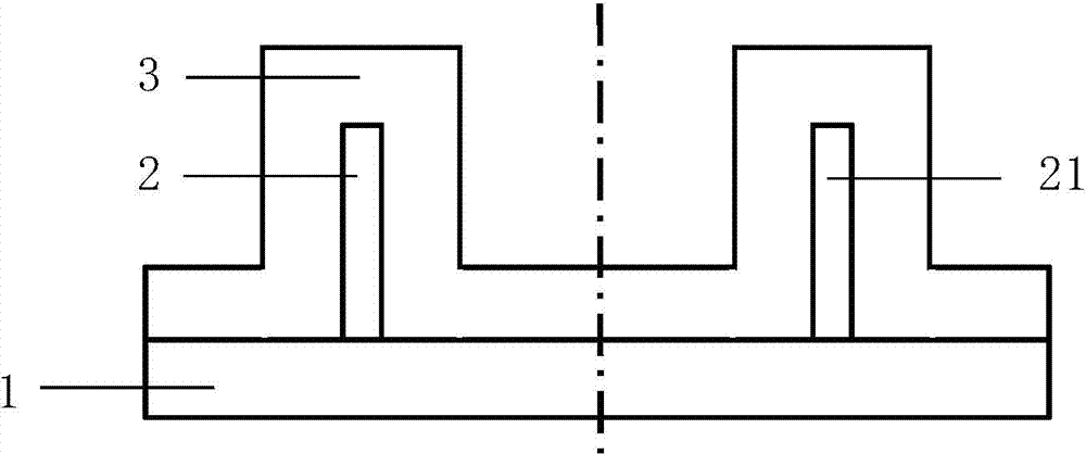
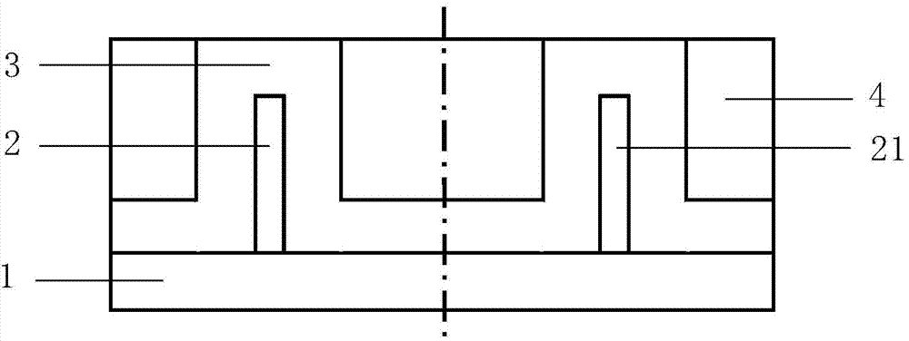
[0029] In the following specific embodiments of the present invention, please refer to figure 1 , figure 1 It is a flowchart of a method for preparing a fin field effect transistor of the present invention. Also, see Figure 2 to Figure 7 , Figure 2 to Figure 7 is a preferred embodiment of the present invention according to figure 1 A schematic...


PUM


Abstract

The invention discloses a method for manufacturing a fin field effect transistor (FET). Polycrystalline silicon layers are deposited on two fin structures of the FinFET twice, a height difference is correspondingly formed above the two fin structures, polycrystalline silicon is etched back by means of the height difference, a gate of one fin structure is divided to form two gates for further formation of a 4T-FinFET, the 4T-FinFET and a 3T-FinFET can be integrated to be manufactured, etching precision can be accurately controlled, damage to a device structure is avoided, and self-alignment is achieved during manufacturing.

Description

technical field [0001] The invention relates to the technical field of semiconductor manufacturing, and more particularly, to a method for preparing a fin field effect transistor. Background technique [0002] In the process of seeking higher device density, higher performance, and lower cost, as the integrated circuit process continues to develop to the nanotechnology process node, some manufacturers have begun to consider how to move from planar CMOS transistors to three-dimensional fin field Transition issues in effect transistor (FinFET) device structures. FinFET is a new type of complementary metal-semiconductor (CMOS) transistor, which can adjust the threshold voltage of the device according to needs, and further reduce static power consumption (static power consumption). Compared with planar transistors, FinFET devices reduce short-channel effects due to improved control of the channel. [0003] Currently, FinFETs generally include three-terminal FinFETs (3terminal ...

Claims


Application Information

Patent Timeline
Patent Type & Authority Applications(China)
IPC IPC(8): H01L21/336
Inventor 鲍宇
Owner SHANGHAI HUALI MICROELECTRONICS CORP
Why Eureka
Try Eureka