Low-coupling dual-frequency antenna array based on H-shaped micro-strip resonator

A technology of dual-frequency antenna and microstrip antenna, which is applied in the directions of antenna array, antenna, antenna coupling, etc., to achieve the effect of increasing cost, easy processing, and reducing coupling coefficient

Inactive Publication Date: 2015-06-17
CHONGQING UNIV
View PDF4 Cites 8 Cited by
  • Summary
  • Abstract
  • Description
  • Claims
  • Application Information

AI Technical Summary

Problems solved by technology

However, most of the existing antenna array decoupling designs are for single-frequenc...

Method used


Image

  • Low-coupling dual-frequency antenna array based on H-shaped micro-strip resonator
  • Low-coupling dual-frequency antenna array based on H-shaped micro-strip resonator
  • Low-coupling dual-frequency antenna array based on H-shaped micro-strip resonator

Examples


Embodiment Construction

[0020] The preferred embodiments of the present invention will be described in detail below with reference to the accompanying drawings.

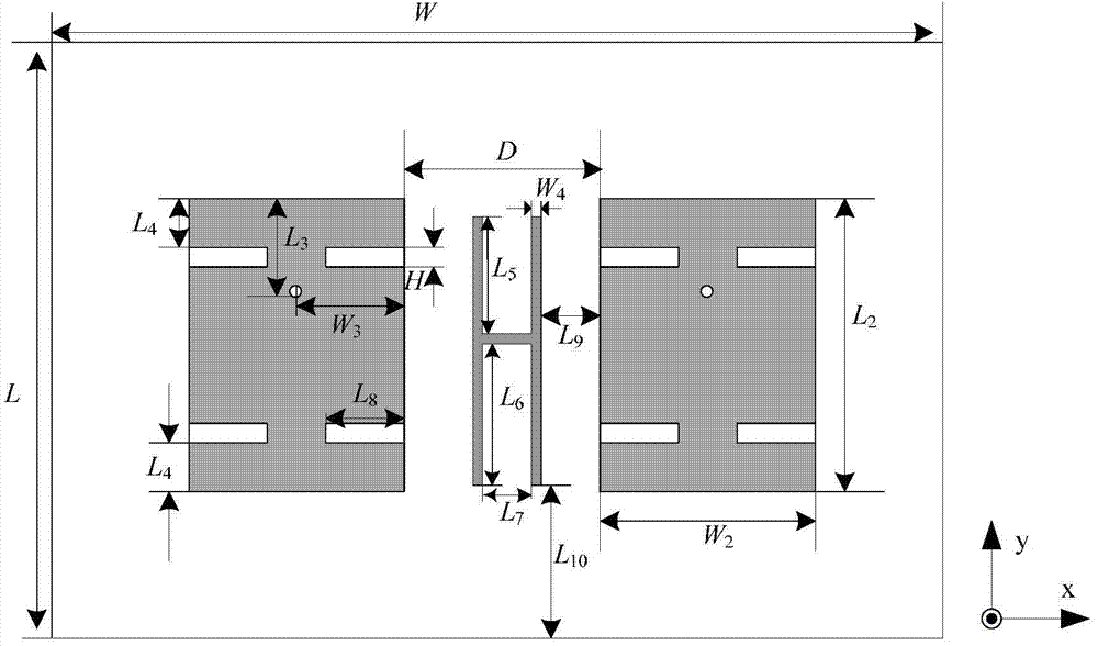
[0021] A kind of low-coupling dual-frequency antenna array based on the H-shaped microstrip resonator provided by the present invention, such as figure 1 As shown, the low-coupling dual-frequency antenna array includes a dielectric substrate, a microstrip antenna unit and an H-shaped microstrip resonator; the H-shaped microstrip resonator is located between the radiating surfaces of the microstrip antenna unit, and the H-shaped microstrip A ribbon resonator can resonate separately at two frequencies.

[0022] The microstrip antenna unit is arranged symmetrically on both sides of the dielectric substrate, the microstrip antenna unit contains a feed point, and the microstrip antenna unit is a rectangular microstrip antenna. The microstrip antenna unit has two operating frequencies. Two rectangular grooves are arranged on the left and right ...


PUM


Abstract

The invention relates to a low-coupling dual-frequency antenna array based on an H-shaped micro-strip resonator, belonging to the technical field of antenna designs. The low-coupling dual-frequency antenna array comprises a dielectric substrate, micro-strip antenna units and the H-shaped micro-strip resonator, wherein the micro-strip antenna units are rectangular micro-strip antennas, are symmetrically arranged at the both sides of the dielectric substrate, and have two working frequencies; the H-shaped micro-strip resonator is located between the micro-strip antenna units and used for generating resonance on the two frequencies respectively, and the formed indirect coupling route counteracts direct coupling between two array elements; the resonant frequency generated by the H-shaped micro-strip resonator can be adjusted by changing the lengths of upper and lower stubs. The low-coupling dual-frequency antenna array based on the H-shaped micro-strip resonator provided by the invention is capable of effectively reducing the coupling coefficient of a micro-strip antenna array without any additional cost, and is easy to process.

Description

technical field [0001] The invention belongs to the technical field of antenna design, and relates to a low-coupling dual-frequency antenna array based on an H-shaped microstrip resonator. Background technique [0002] Planar microstrip patch antennas are very popular in many communication and radar applications. Multi-port antenna systems are widely used in modern wireless communication systems due to their advantages of high speed and large capacity. However, installing multiple antennas on a terminal device of limited size is not an easy task. This is because as the distance between the elements of the antenna decreases, the electromagnetic coupling between the elements becomes very strong, which greatly affects the performance of the antenna and the entire communication system. Therefore, the design of multi-antenna array needs to consider and reduce the mutual coupling between array elements. There are several techniques for reducing mutual coupling in compact antenn...

Claims


Application Information

Patent Timeline
IPC IPC(8): H01Q1/52H01Q21/00
Inventor 于彦涛顾兆凯易礼君刘晓亚
Owner CHONGQING UNIV
Why Eureka
Try Eureka