Adsorption device and adsorption method

An adsorption device and adsorber technology, applied in chemical instruments and methods, cleaning methods and utensils, cleaning methods using liquids, etc., can solve the problems of large-scale and fast-paced production requirements, high time ratio of slag discharge, The reduction of equipment processing capacity and other problems can achieve the effect of enhancing multi-tasking versatility, high efficiency of slurry filtration, and smooth flow of slurry.

Active Publication Date: 2015-06-24
广州粤有研矿物资源科技有限公司
View PDF7 Cites 5 Cited by
  • Summary
  • Abstract
  • Description
  • Claims
  • Application Information

AI Technical Summary

Problems solved by technology

Its working method is as follows: a working cycle is divided into two stages, the first stage is the slurry feeding stage, and the slurry is fed when the magnet is turned on; the second stage is the slag discharge stage, and the slag is discharged when the magnetism is off. Iron removal operation, which causes a decline in equipment processing capacity
After industrial debugging, when the equipment has a good sorting index, the time ratio of pulp feeding and slag discharge is 11:7, and the time ratio of slag discharge is relatively high, which cannot meet the needs of large-scale and fast-paced production

Method used


Image

  • Adsorption device and adsorption method
  • Adsorption device and adsorption method
  • Adsorption device and adsorption method

Examples


Embodiment 1

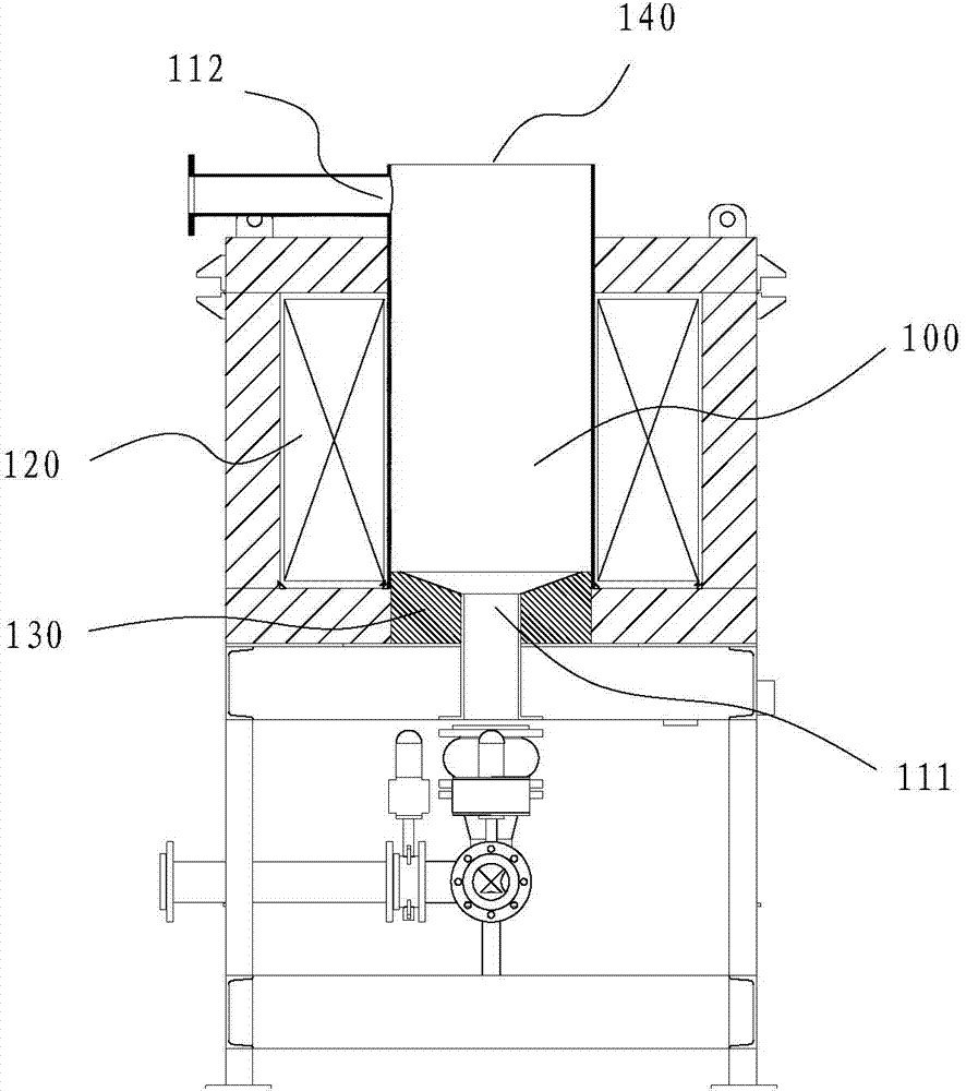
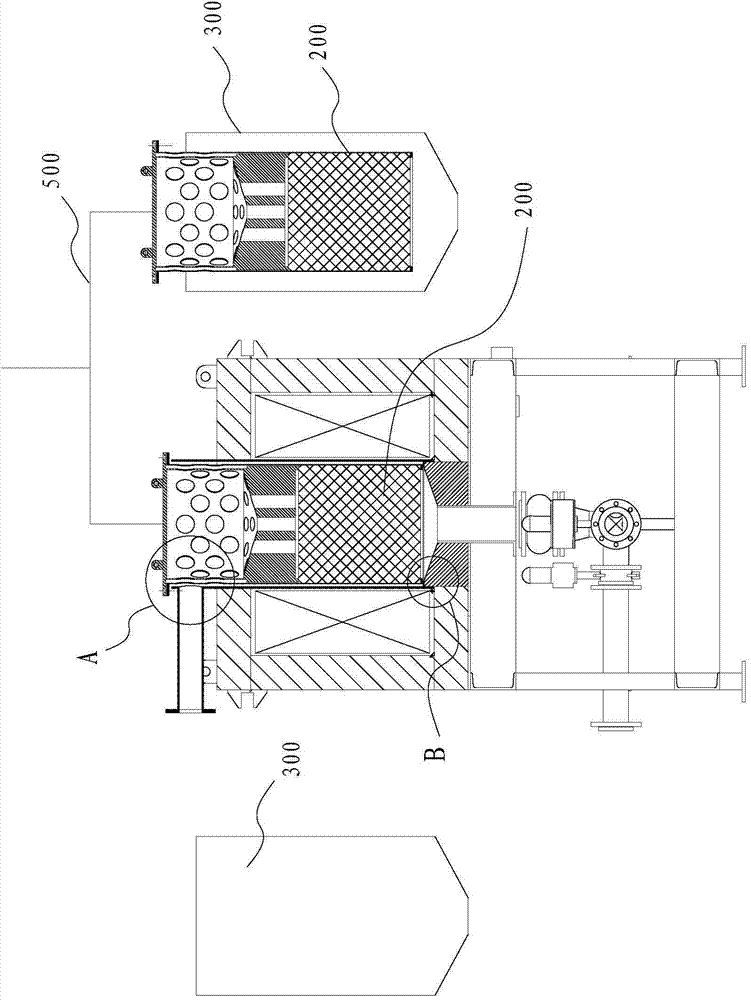
[0044] The adsorption device includes: an adsorption chamber 100 , an adsorber 200 , a cleaning station 300 and a switching device 500 .

[0045] The adsorption chamber 100 is an upright cylindrical cavity.

[0046] The bottom surface of the lower part of the adsorption chamber 100 is provided with a first liquid inlet 111, and the first liquid inlet 111 is connected with a liquid inlet pipe for sending the original slurry into the adsorption chamber 100; the lower part of the adsorption chamber 100 is also provided with a first magnetic yoke 130 , the first magnetic yoke 130 is provided with a central through hole, the liquid inlet pipe passes through the central through hole of the first magnetic yoke 130 , and the first magnetic yoke 130 is welded and sealed with the side wall of the adsorption chamber 100 .

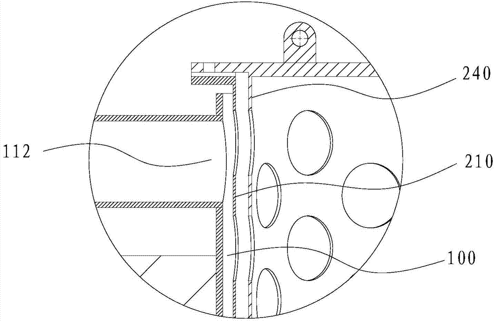
[0047]The side of the upper part of the adsorption chamber 100 is provided with a first liquid outlet 112 , and the first liquid outlet 112 is connected with a liquid...

Embodiment 2

[0071] The difference between embodiment two and embodiment one is:

[0072] Only one cleaning station 300 is provided, and the cleaning station 300 is arranged in parallel with the adsorption chamber 100 .

[0073] The switching device is provided with a lifting mechanism and a rotating mechanism, and the rotation center of the rotating mechanism is at the center of the line connecting the cleaning station 300 and the adsorption chamber 100 .

[0074] At the beginning, the first adsorber is adsorbed in the adsorption chamber, and the second adsorber is in the cleaning station; when the first adsorber is fully loaded, the first adsorber and the second adsorber are lifted at the same time, and the rotating mechanism is used to move the The first adsorber and the second adsorber are rotated 180 degrees so that the positions of the two are reversed. At this time, the first adsorber is aligned with the cleaning station and the second adsorber is aligned with the adsorption chamber...

Embodiment 3

[0076] The difference between embodiment three and embodiment one is:

[0077] The switching device is provided with a lifting mechanism and a rotating mechanism. The first cleaning station and the second cleaning station are located on both sides of the adsorption chamber 100. The first cleaning station, the second cleaning station, and the adsorption chamber are based on the rotation center of the rotating mechanism The centers are arranged in circles.

[0078] At the beginning, the first adsorber is adsorbed in the adsorption chamber, and the second adsorber is in the second cleaning station;

[0079] When the first adsorber is fully loaded, lift the first adsorber and the second adsorber at the same time, and use the rotating mechanism to rotate the first adsorber and the second adsorber several degrees so that the positions of the two are reversed. At this time, the first adsorber Align the first cleaning station, the second adsorber to the adsorption chamber, and use th...


PUM


Abstract

The invention discloses an adsorption device and an adsorption method. The adsorption device comprises an adsorption chamber, at least two adsorbers, a cleaning station and a switching device, wherein liquid is fed into the adsorption chamber from a first liquid inlet, when the liquid flows through the adsorbers, impurities in the liquid are attached to the adsorbers, and then the liquid subjected to adsorption and filtering flows out of a first liquid outlet; and after one adsorber adsorbs impurities, the switching device is adopted for switching the adsorber from the adsorption chamber to the cleaning station, and after the other adsorber is switched to the adsorption chamber, a cleaning device is adopted for cleaning the adsorbers. The cleaning station and the adsorption chamber are independently arranged, and the cleaning process of the adsorber does not take up the impurity adsorption time, so that the iron removal efficiency is greatly improved; and the device is simple in structure, easy to control and convenient to maintain.

Description

technical field [0001] The invention belongs to the field of slurry processing, and in particular relates to an adsorption device and method. Background technique [0002] At present, for the iron removal of non-metallic mines, the intermittent electromagnetic iron remover that continuously repeats the cycle of pulp feeding and slag discharge is widely used. Its working method is as follows: a working cycle is divided into two stages, the first stage is the slurry feeding stage, and the slurry is fed when the magnet is turned on; the second stage is the slag discharge stage, and the slag is discharged when the magnetism is off. Iron removal operation, which results in a decline in equipment processing capacity. After industrial debugging, when the equipment has a good sorting index, the time ratio of pulp feeding and slag discharge is 11:7, and the time ratio of slag discharge is relatively high, which cannot meet the needs of large-scale and fast-paced production. Conten...

Claims


Application Information

Patent Timeline
Patent Type & Authority Applications(China)
IPC IPC(8): B03C1/02B08B3/04
Inventor 许丽敏林恬盛王丽娟徐少华赵明何建全陈俊明王威吴城材钟森林朱远标周庆红张超达
Owner 广州粤有研矿物资源科技有限公司
Why Eureka
Try Eureka