
A prestressed assembled concrete beam-column joint structure and its construction method

A construction method and a technology of beam-column joints, applied in the direction of building construction and construction, can solve problems such as weak energy consumption, and achieve the effects of convenient construction operation, uniform force transmission, and low prestress loss

Inactive Publication Date: 2017-03-22
WUHAN UNIV OF TECH
View PDF5 Cites 0 Cited by
  • Summary
  • Abstract
  • Description
  • Claims
  • Application Information

AI Technical Summary

Problems solved by technology

[0004] Previous experimental studies have shown that prestressed prefabricated joints exhibit nonlinear elastic mechanical properties and have high deformation recovery capabilities, but their energy dissipation capabilities are weak, and they are prone to large deformations under earthquakes

Method used


Image

  • A prestressed assembled concrete beam-column joint structure and its construction method
  • A prestressed assembled concrete beam-column joint structure and its construction method
  • A prestressed assembled concrete beam-column joint structure and its construction method

Examples


Embodiment Construction

[0026] In order to have a clearer understanding of the technical features, purposes and effects of the present invention, the specific implementation manners of the present invention will now be described in detail with reference to the accompanying drawings.

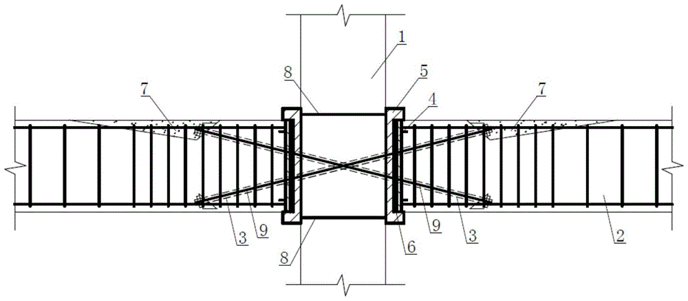
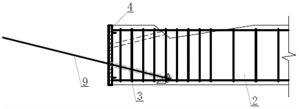
[0027] like Figure 1-Figure 3 As shown, the prestressed prefabricated concrete beam-column joint structure of the present invention includes a prefabricated column 1 passing through the joint area, a prefabricated beam 2 arranged on both sides of the joint, a prestressed steel bar 9, and a beam end integrally cast with the prefabricated beam 2 Steel plate 4, channel-shaped steel plate 5 on both sides of the node that is welded and connected with steel bars 8 and cast together with the column, high damping rubber layer 6, concrete post-casting belt 7 in the tension anchorage area.

[0028] Channel steel 5 is buried on both sides of the joint between prefabricated column 1 and prefabricated beam 2, and the channel steel ...


PUM


Abstract

The invention relates to a prestress assembled concrete beam column joint structure and a construction method thereof. The prestress assembled concrete beam column joint structure comprises a prefabricated column and a prefabricated beam. The prefabricated beam and the prefabricated column are in prepressing connection through the prestress formed by tensioning prestressed reinforced steel bars. The bottom of the beam end on one side of a joint is connected with the top of the beam end on the other side of the joint through the prestressed reinforced steel bars, and the prestressed reinforced steel bars are symmetrically crossed on a vertical face. When the prefabricated beam is manufactured, the prestressed reinforced steel bars and anchoring parts of the prestressed reinforced steel bars are pre-buried at the bottom of the beam end, prestressed reinforced steel bar pore channels and an anchoring area are reserved in the top of the beam end, and open type stirrups are adopted in the anchoring area. A force transmission steel plate is arranged on the cross section part of the beam end by the way that the cross section part of the beam end is welded with longitudinal bars. Slant prestressed reinforced steel bar pore channels are reserved in a prefabricated column joint area, groove-shaped steel plates are pre-buried on the two sides of the joint of the column, and high damping rubber layers are attached to the insides of the groove-shaped steel plates. In the connecting process, the beam is clamped into channel steel, and the prestressed reinforced steel bars penetrate through a joint core area to the top of the beam end on the other side of the joint and are anchored after being tensioned to be at the designed stress. According to the prestress assembled concrete beam column joint structure and the construction method thereof, assembling construction is convenient, and high shear-bearing capacity, energy-dissipating capacity and self-resetting capacity of the connecting joint can be achieved.

Description

technical field [0001] The invention relates to a prestressed assembled concrete beam-column node structure and a construction method thereof in the field of construction. Background technique [0002] The prefabricated concrete structure refers to the structural system in which the main load-bearing components of the structural system, such as beams, columns, walls, etc., are prefabricated and transported to the construction site for assembly. Prefabricated concrete structures are being rapidly popularized and applied due to their advantages of energy saving, environmental protection, and little impact on the construction environment. In terms of the mechanical properties of the structure, the key issue of the prefabricated structure is the reliability of the connecting nodes. Previous structural earthquake damages have shown that the main cause of failure of most prefabricated structures is the failure of the structural system due to the failure of the beam-column joints. ...

Claims


Application Information

Patent Timeline
Patent Type & Authority Patents(China)
IPC IPC(8): E04B1/21
Inventor 蒲武川陈向谷倩梁瑞军
Owner WUHAN UNIV OF TECH
Learn More