
Full-automatic mortar conveying machine capable of automatically controlling conveying amount

A fully automatic, high-capacity delivery technology, which is applied in the processing of building materials, construction, building construction, etc., can solve the problems of heavy workload of pumping workers, waste of electric energy and mortar, and high labor intensity of construction workers. The working process is stable and reliable, the replacement is quick and convenient, and the maintenance cost is low.

Inactive Publication Date: 2015-06-24
胡维毅
View PDF13 Cites 4 Cited by
  • Summary
  • Abstract
  • Description
  • Claims
  • Application Information

AI Technical Summary

Problems solved by technology

[0005] As we all know, the construction process of high-rise buildings is generally: pump the mortar mixed with continuous mixer, turnover box, etc. from the ground to the specific construction floor through pumping equipment such as mortar conveyor, and the construction workers will pump it to the ground of the floor The mortar is put into the mortar spraying machine, and the mortar is sprayed onto the wall by the similar mortar spraying machine as disclosed in CN203613772U. When the workers stop work halfway, in order to prevent the mortar from solidifying in the pipeline of the pumping equipment, special personnel need to be separated for a period of time. Turn on the pumping equipment once, and put the pumping equipment pipeline leading to the construction floor into the mortar collection box in advance. At the end of the work at noon or afternoon, you need to connect the mortar inlet of the pumping equipment to the water pipe and start the pumping equipment Flush the mortar in the pipeline of the pumping equipment through the pressure of water. When starting work the next day, connect the inlet of the mortar to the turnover box, and flush out the water in the pipeline of the pumping equipment through the mortar to start normal operation. Pumping operation, it can be seen that the workload of pumping workers is relatively large. When the pumping equipment is stopped, the pipeline of the pumping equipment is easily blocked by the solidified mortar, which leads to failure, and wastes power energy and mortar.
[0006] Moreover, through the construction process of the pumping equipment, at least two people are required to cooperate in each group of spraying construction. The workers who load the mortar must continuously load the mortar into the mortar spraying machine. The labor intensity of the construction workers is high and the construction efficiency is low. If the same floor needs to There are many walls to be sprayed, but the mortar spraying machine can only be connected to one spray gun, so that multiple mortar spraying machines are required to spray at the same time, the number of equipment and workers required is large, the construction cost is large, and each floor The construction needs to lay the pumping pipeline in advance, which is time-consuming and labor-intensive. In order to prevent the instantaneous pressure loss of the double piston rod during suction and discharge, the pumping continuity of the pumping equipment is poor. In order to ensure the piston mortar pump Continuous operation, the general pumping equipment is equipped with an air pressure balance regulating tank for supplementing the lack of pressure on the discharge pipeline, but once the air pressure balance regulating tank leaks into the mortar, the entire equipment will be paralyzed, while the existing pumping equipment There is no solution to this problem. Due to the huge pipeline pressure of the pumping equipment, there is currently no technology that can directly connect the mortar delivery pipeline of the pumping equipment to the mortar spraying machine or spray gun for secondary loading without mortar spraying operation, which has always been a big problem for technicians in the construction industry

Method used


Image

  • Full-automatic mortar conveying machine capable of automatically controlling conveying amount
  • Full-automatic mortar conveying machine capable of automatically controlling conveying amount
  • Full-automatic mortar conveying machine capable of automatically controlling conveying amount

Examples


Embodiment Construction

[0025] Below in conjunction with accompanying drawing and specific embodiment the present invention is described in further detail;

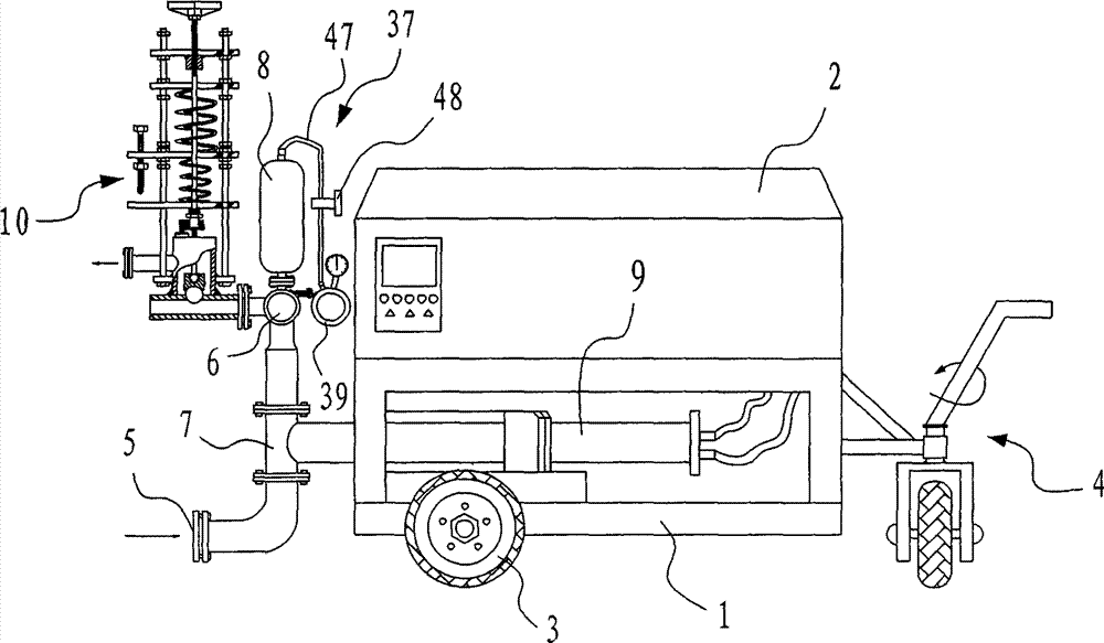
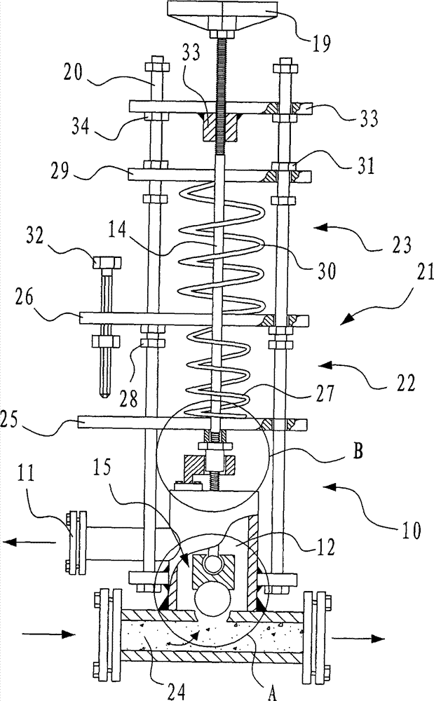
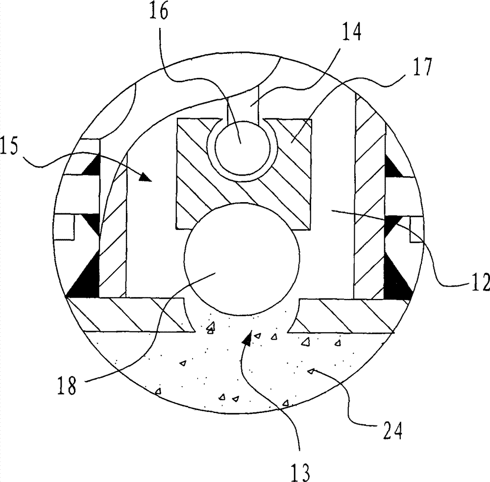
[0026] Such as figure 1 , 2 , 3, 4, 5, and 6, a fully automatic mortar conveyor with automatic control of the delivery volume includes a housing 2 with a base 1, and transport wheels 3 for easy movement are installed on both sides of the base 1, and on the base The end of 1 is equipped with a universal wheel mechanism 4 for easy turning. On the base 1, there are mortar main pipes 7 connected to each other with a mortar suction port 5 and a mortar delivery port 6. Usually, the mortar suction port 5 is connected to a continuous mixer. The turnover box, the mortar delivery port 6 is connected to the mortar collection place of the specific construction site through the pumping equipment pipeline, and the mortar delivery port 6 of the present invention can be directly connected to the spray gun or the mortar spraying machine through the pumping equi...


PUM


Abstract

The invention discloses a full-automatic mortar conveying machine capable of automatically controlling the conveying amount. The full-automatic mortar conveying machine comprises a dual-piston cylinder body arranged on a base and used for sucking and discharging mortar. The dual-piston cylinder body is connected with a mortar main pipe. The mortar main pipe is provided with an automatic mortar flow adjusting device which achieves automatic overflowing when pressure produced by the minimum mortar spraying quantity in unit time in the mortar main pipe exceeds the maximum mortar spraying quantity in unit time of a single spraying gun. The mortar main pipe is provided with a pressure sensor, wherein the pressure sensor automatically sends an electric signal to control a motor to be decelerated to be at the minimum rotating speed when the largest pressure in the mortar main pipe is detected. The pressure sensor is in signal connection with a frequency conversion device through a controller, wherein the frequency conversion device controls the rotating speed of the motor. The spraying gun or a mortar spraying machine is directly connected to a pumping device, the unsolved problem which people hope earnestly to solve for a long time is solved, and the full-automatic mortar conveying machine is worthy of application and popularization.

Description

technical field [0001] The invention relates to the technical field of construction machinery, in particular to a fully automatic mortar conveyor with automatic control of the conveying volume. Background technique [0002] With the rapid development of my country's economic construction, the market demand for material pumping equipment is increasing. Piston mortar pump has the advantages of strong wear resistance, high working efficiency, large working pressure, large flow, convenient operation, safety and reliability, compact structure, convenient and flexible movement, and easy maintenance. has been more widely used. Therefore, pumping equipment such as mortar pumps and mortar conveyors came into being. [0003] Pumping equipment generally includes a main cylinder with a main piston inside. The delivery piston is located in the delivery cylinder. The delivery piston is connected to the main piston through a piston rod and can reciprocate in the delivery cylinder. The de...

Claims


Application Information

Patent Timeline
IPC IPC(8): E04G21/02
Inventor 胡维毅胡林胡国
Owner 胡维毅
Learn More