Side wall circulation combustion chamber for diesel engine

A diesel engine, combustion chamber technology, applied in combustion engines, machines/engines, internal combustion piston engines, etc., can solve problems affecting the rationality of airflow movement organization, the uniformity of mixture distribution, the further improvement of thermal efficiency, and the insufficiency of the combustion process. To achieve the effect of promoting atomization and spatial mixing and distribution, reducing carbon deposition, and reducing local combustion high temperature areas

Inactive Publication Date: 2015-06-24
NORTH CHINA UNIV OF WATER RESOURCES & ELECTRIC POWER
View PDF7 Cites 0 Cited by
  • Summary
  • Abstract
  • Description
  • Claims
  • Application Information

AI Technical Summary

Problems solved by technology

[0005] The shape and structure of the existing diesel engine combustion chamber is simple, and the effect of the deep pit design of the combustion chamber on improving the combustion process is limited. Especially, the space of the combustion chamber of the high-speed diesel engine is relatively small, the K coefficient of the combustion chamber is low, the air utilization rate is not high, and the combustion process The organization is more difficult, and the thermal efficiency cannot be improved. For high-pressure injection, there is still a phenomenon that the fuel beam hits the wall more seriously, and the shape of the combustion chamber affects the rationality of the airflow movement organization and the uniformity of the distribution of the mixture in the combustion chamber space. As a result, the air utilization rate in the combustion chamber is low, the combustion process cannot be fully carried out, resulting in poor engine emissions, high fuel consumption, and no further improvement in thermal efficiency

Method used


Image

  • Side wall circulation combustion chamber for diesel engine
  • Side wall circulation combustion chamber for diesel engine

Examples


Embodiment Construction

[0019] The present invention will be described in further detail below in conjunction with the accompanying drawings.

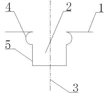
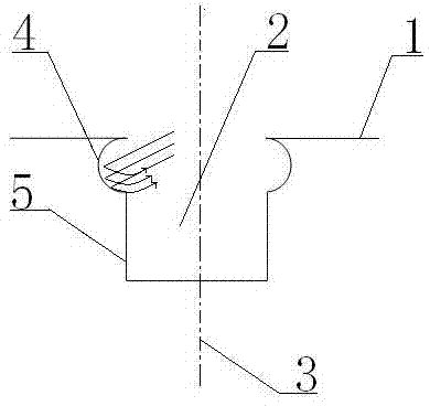
[0020] Such as figure 1 , figure 2 As shown in the side wall circulation combustion chamber of the diesel engine, the depth of the upper end surface of the side wall circulation combustion chamber of the diesel engine from the upper bottom surface of the piston chamber is 24mm ~ 26mm; the side wall circulation combustion chamber of the diesel engine is opened in The concave deep pit 2 on the top of the piston 1, the concave deep pit 2 is symmetrical about the central axis 3 of the piston; the concave deep pit 2 includes an annular part 4 and a columnar part 5; Symmetrical semi-circular arc, the diameter of the semi-circular arc-shaped annular part 4 is 7 mm to 8 mm, the center of the semi-circular arc is located on the side of the longitudinal section of the concave deep pit 2, and the upper part of the semi-circular arc is formed with the longitudinal sect...


PUM


Abstract

The invention mainly relates to the technical field of diesel engines, in particular to a side wall circulation combustion chamber for a diesel engine. The side wall circulation combustion chamber for the diesel engine is a concave deep pit which is formed in the top of a piston. The concave deep pit is symmetric about the central axis of the piston. The concave deep pit comprises an annular part and a columnar part. The shape of the longitudinal section of the annular part is a semicircle which is symmetric about the central axis of the piston. The circle center of the semicircle is positioned on the side edge of the longitudinal section of the concave deep pit. The upper portion of the semicircle is tangent to a straight line formed by the longitudinal section of the end face on the top of the piston. The columnar part is cylinder-shaped. The side edge of the longitudinal section of the columnar part is connected with the lower portion of the semicircle. The side edge of the longitudinal section of the columnar part and the circle center of the semicircle of the longitudinal section of the annular part are in the same vertical straight line. According to the side wall circulation combustion chamber for the diesel engine, the structure is simple and compact, the layout is reasonable, when diesel is injected into the side wall circulation combustion chamber, diesel sprays are injected to the arc surface of the side wall of the side wall circulation combustion chamber, then the rebound is generated, and circulation is generated in the side wall circulation combustion chamber, so that mixing of the diesel and air is more even, and the efficient combustion of the diesel is facilitated.

Description

technical field [0001] The invention mainly relates to the technical field of diesel engines, in particular to a side wall circulation combustion chamber of a diesel engine. Background technique [0002] Diesel engines are widely used in large and medium-sized vehicles because of their high power and good economic performance. But diesel engines have always given the impression of being bulky, noisy and smoky. At present, with the improvement of national emission regulations and stricter control of NOx and particle emissions, it is imperative to develop low-emission diesel engines. [0003] In recent years, diesel engines have adopted advanced technologies such as turbocharging, intercooling, direct injection, catalytic conversion of exhaust gas and particulate traps, and the emission problems of diesel engine vehicles have gradually been solved. However, in the final analysis, the exhaust emissions of diesel engines lie in the mixed gas Whether it can be mixed evenly ...

Claims


Application Information

Patent Timeline
Patent Type & Authority Applications(China)
IPC IPC(8): F02B23/02
CPCY02T10/12
Inventor 彭晗孙志强秦高林姚林晓上官林建吴金妹金阳
Owner NORTH CHINA UNIV OF WATER RESOURCES & ELECTRIC POWER
Why Eureka
Try Eureka