Simple photovoltaic, photothermal and thermoelectric comprehensive utilization system

A simple, photovoltaic technology, applied in the field of solar energy utilization, can solve the problems of low power generation and heat collection efficiency, complex structure, etc., and achieve the effects of high automation, increased heating area, and increased utilization rate

Active Publication Date: 2015-06-24
ANHUI UNIVERSITY OF TECHNOLOGY
View PDF11 Cites 6 Cited by
  • Summary
  • Abstract
  • Description
  • Claims
  • Application Information

AI Technical Summary

Problems solved by technology

[0007] The purpose of the present invention is to overcome the complex structure of solar energy comprehensive utilization devices in the prior art and the shortcomings of low power generation and heat collection efficiency, and provide a simple photovoltaic-photothermal-thermoelectric comprehensive utilization system. The technical solution of the present invention simplifies the heat collection The internal structure and system composition of the power generation components, through the organic combination of various devices, realize the functions of photovoltaic power generation, thermoelectric power generation and solar heating, increase the utilization rate of solar energy, improve the efficiency of thermal power generation, and reduce costs

Method used


Image

  • Simple photovoltaic, photothermal and thermoelectric comprehensive utilization system
  • Simple photovoltaic, photothermal and thermoelectric comprehensive utilization system
  • Simple photovoltaic, photothermal and thermoelectric comprehensive utilization system

Examples


Embodiment 1

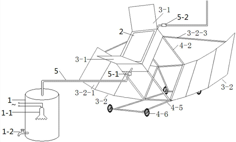
[0034] see figure 1 , a simple photovoltaic-solar-thermal-thermoelectric comprehensive utilization system in this embodiment is mainly composed of a support frame, a concentrating device, a heat collecting power generation module 2 and a hot water collecting device, etc., the concentrating device and heat collecting The power generation component 2 is installed on the support frame, and the light collected by the concentrating device is irradiated on the outer surface of the heat collection power generation component 2 to provide energy for power generation and heat collection, and the hot water in the heat collection power generation component 2 is transported to the Hot water collection device.

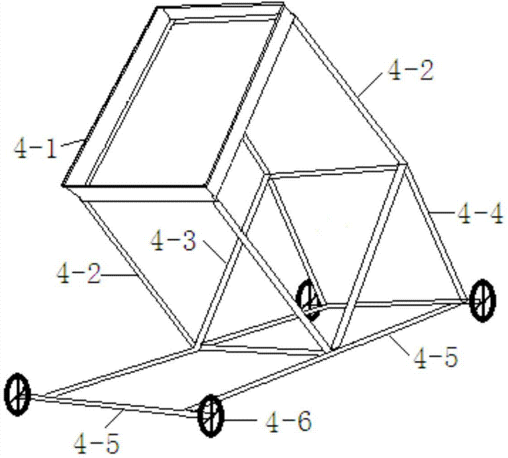
[0035] see figure 2 , the support frame in this embodiment includes a top fixed frame 4-1, a fixed frame support 4-2, a lower reflector mounting frame 4-3, an angle adjustment frame 4-4 and a bottom frame 4-5, and the bottom frame 4 Bottom wheels 4-6 are installed on the -5, and ...

Embodiment 2

[0046] A simple photovoltaic-photothermal-thermoelectric comprehensive utilization system of this embodiment has basically the same structure as that of Embodiment 1, the difference being that the plane mirror 3-2 set by the lower reflector 3-2 in this embodiment 2-1 has two.


PUM


Abstract

The invention discloses a simple photovoltaic, photothermal and thermoelectric comprehensive utilization system and belongs to the field of solar energy utilization. The system comprises a supporting frame, a condensation device, a heat collection and power generation module and a hot water collection device, wherein the condensation device and the heat collection and power generation module are installed on the supporting frame, a planar reflector is installed in the condensation device, converged light rays irradiate the outer surface of the heat collection and power generation module, a heat collection water tank is arranged in the heat collection and power generation module, the heat collection water tank is communicated with the hot water collection device through a water delivery pipe, and a photovoltaic module and a thermoelectric module which are used for power generation are arranged on the two sides of the water tank respectively. The internal structure and system composition of the heat collection and power generation module are simplified; the devices are organically combined, so that the functions of photovoltaic power generation, thermoelectric power generation and optical energy heating are achieved, the utilization rate of solar energy is increased, heat collection and power generation efficiency is improved, and cost is reduced.

Description

technical field [0001] The invention relates to the technical field of solar energy utilization, and more specifically, relates to a simple photovoltaic-photothermal-thermoelectric comprehensive utilization system. Background technique [0002] Solar heat collection technology is constantly developing and innovating, and is widely used in various fields of the national economy. Especially in the civil field, the application of solar cookers has been recognized by people, bringing real convenience to people's lives. The principle of ordinary solar photovoltaic cell power generation is that sunlight shines on the photovoltaic cell through the cover plate and EVA. After the photovoltaic cell absorbs the transmitted sunlight energy, less than 20% of it is converted into electrical energy, and the rest is converted into heat and absorbed by the battery module. , and finally lost in the air. If it cannot be utilized, on the one hand, it will cause a large waste, on the other hand...

Claims


Application Information

Patent Timeline
Patent Type & Authority Applications(China)
IPC IPC(8): F24J2/00F24J2/10F24J2/40F24J2/46F24J2/52H02S10/10F24S23/70
CPCY02B10/20Y02E10/47Y02E10/50
Inventor 贾虎袁银梅
Owner ANHUI UNIVERSITY OF TECHNOLOGY
Why Eureka
Try Eureka