

Refrigerating equipment
A technology for refrigeration equipment and liner, which is applied to household refrigeration devices, lighting and heating equipment, coolers, etc., can solve the problems of increased cost, limited improvement in anti-cracking effect, etc., and achieves low cost, alleviation of liner cracking, and production method. simple effect
- Summary
- Abstract
- Description
- Claims
- Application Information
AI Technical Summary
Problems solved by technology
Method used
Image

Examples
Embodiment 1
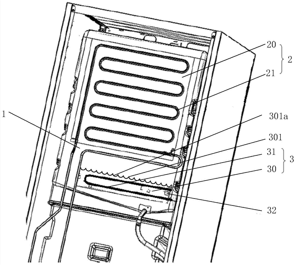
[0048] figure 2 Shown is a schematic structural diagram of the refrigeration equipment provided in this embodiment.
[0049] The refrigeration equipment includes:
[0050] Liner 1;
[0051] The evaporator 2 connected to the inner tank 1;
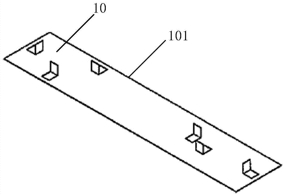
[0052] A heating device 3, there is a distance between the heating device 3 and the evaporator 2, the heating device 3 includes a heat conducting plate 30 fixed to the inner tank 1 and a heat source connected to the heat conducting plate 30;
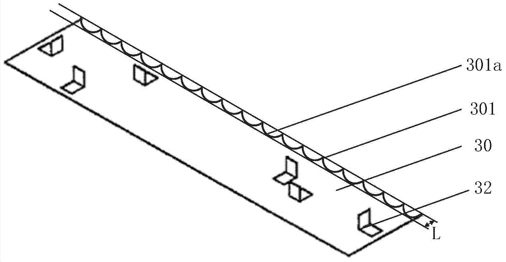
[0053] Wherein, the heat conducting plate 30 has at least one notch on the side 301 near the evaporator 2 .
[0054]Specifically, refer to figure 2 As shown, the evaporator 2 is one of the core components of the refrigeration equipment, including a heat exchange plate 20, and a pipe fitting fixed on one side of the heat exchange plate 20, such as an aluminum tube 21, through which liquid refrigerant flows in the aluminum tube 21, and the gas heat absorption, so that the temperature of the inner ...
Embodiment 2
[0068] The refrigeration equipment provided in the second embodiment is roughly the same as the refrigeration equipment in the first embodiment, the difference is that, as Figure 4 and Figure 5 As shown, the notches of the plurality of arc-shaped structures 301a are not directly connected, but adjacent notches are connected by a straight line connecting portion 301b.
[0069] The above-mentioned linear connection portion 301b makes the distance between the connection point (virtual) of two adjacent arc-shaped structures 301a and the bottom of the arc-shaped structure 301a larger, which increases the bandwidth L of the thermal temperature gradient distribution range in a disguised form, thus further reducing the pressure of the inner tank 1. cracking.
[0070] In other embodiments, a part of the side 301 may be directly connected with a cutout of the arc-shaped structure 301a, or a part of the region of the side 301 may be connected with the straight-line connection part 301...
Embodiment 3
[0072] The refrigeration equipment provided in the third embodiment is roughly the same as the refrigeration equipment in the first embodiment, the difference is that, as Figure 6 and Figure 7 As shown, the notch of the heat conducting plate 30 on the side 301 near the evaporator 2 is a V-shaped structure 301c. The V-shaped structure 301c can be realized by cutting off some triangles on the side 301. The above-mentioned structure utilizes the stability of the triangles, making it difficult for the liner 1 to crack along the direction AB from one end to the other end of the side 301 of the heat conducting plate 30. .
[0073] In this embodiment, two adjacent V-shaped structures 301c are directly connected, that is, form a zigzag shape, and the thermal temperature gradient distribution range formed by the zigzag side 301 is from the tip of a V-shaped structure 301c to the V-shaped structure 301c A strip of width L between the connection point with the adjacent V-shaped struc...
PUM
 Abstract
Description
Claims
Application Information