
Impeller type counter-flow drier

An impeller type, dryer technology, applied in the direction of drying solid materials, drying gas layout, drying, etc., can solve the problems of inconvenient operation and maintenance, low drying efficiency, large plant area, etc., and achieve excellent drying and cooling effect of materials , The effect of low later use and maintenance costs, and simple equipment operation and maintenance

Inactive Publication Date: 2015-06-24
赵兴军 +1
View PDF9 Cites 4 Cited by
  • Summary
  • Abstract
  • Description
  • Claims
  • Application Information

AI Technical Summary

Problems solved by technology

Causes low drying efficiency and poor effect
[0005] 2. The flat-panel dryer consumes high power and occupies a large area of ​​the factory building, about 15-18 meters long and 3.5-4 meters wide.
Moreover, there are many supporting facilities and complex structures
Make its scope of application and occasions limited
[0006] 3. The structure of the counterfeit cooler is complex, and it is necessary to set up a bulk material device driven by a geared motor, a scraper, a hydraulic control station, a hydraulic control mechanism, a PLC electrical control system and other complex mechanisms, which are extremely inconvenient to operate and maintain.
[0007] 4. The power consumption of the counterfeit dryer is high, the bulk material device and the scraper are at least 2.2kw, the hydraulic control station is 3.0kw, and the power consumption of the Fengfeng device is 5.5kw-7.5kw, totaling 10.7kw-12.7kw
[0008] Therefore, the existing reversible dryers and flat-plate dryers are large in size, high in energy consumption, low in efficiency, high in operation and maintenance costs, and cannot meet the operational needs of drying and cooling materials.

Method used


Image

  • Impeller type counter-flow drier
  • Impeller type counter-flow drier
  • Impeller type counter-flow drier

Examples


Embodiment 1

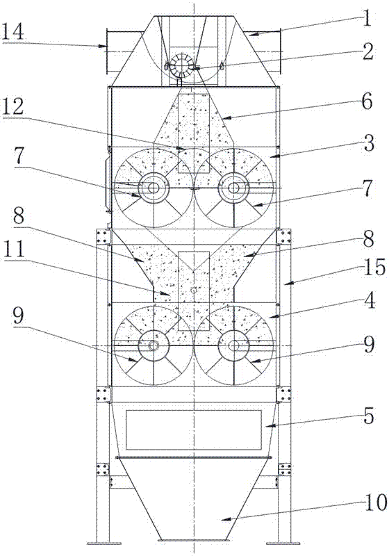
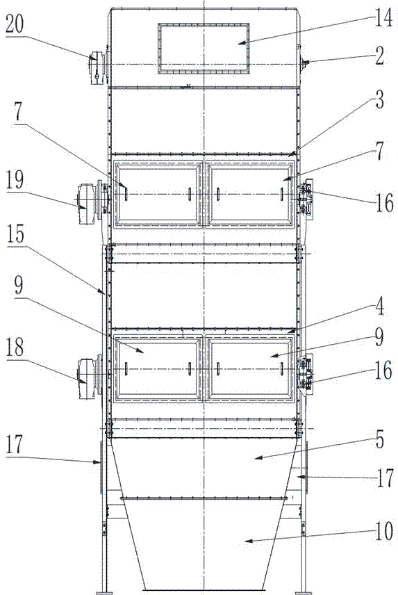
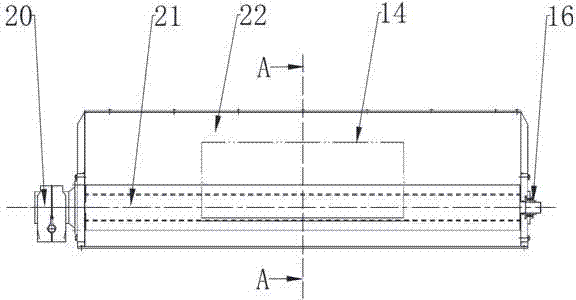
[0045] The impeller type countercurrent dryer includes a frame 14. The frame 14 is sequentially provided with a suction system 1, a Guanfeng feeding system 2, a first dynamic cooling and drying chamber 3, a second dynamic cooling and drying chamber 4 and hot air from top to bottom. Storehouse 5; the side of frame 14 is provided with an airtight shell; hot air storehouse 5 blows hot air for drying and cooling into the shell, and the hot air passes through the second dynamic cooling and drying storehouse 4, the first dynamic cooling and drying storehouse from bottom to top The bin 3 and the dried materials are finally discharged through the suction system 1; the lower part of the hot air bin 5 is provided with a feeder 10 for outputting the dried materials. The material to be dried moves from top to bottom, and is dried and sprinkled by the first dynamic cooling and drying chamber 3 and the second dynamic cooling and drying chamber 4. The hot drying air passes through the materia...


PUM


Abstract

The invention discloses an impeller type counter-flow drier. The impeller type counter-flow drier comprises a rack, the rack is provided with an air draft system, a feeder feeding system, a first dynamic cooling and drying cabin, a second dynamic cooling and drying cabin and a hot wind cabin; a hermetic shell body is arranged on the side of the rack, hot wind used for drying and cooling is blew into the shell body by the hot wind cabin; the hot wind penetrates through the second dynamic cooling and drying cabin and the first dynamic cooling and drying cabin in sequence from top to bottom, the moisture, heat and temperature of dried material are discharged through the air draft system finally; the first dynamic cooling and drying cabin and the second dynamic cooling and drying cabin are internally provided with impeller type rotary feeders. According to the impeller type counter-flow drier, the material drying and cooling effect is good, the production output is large, the power consumption is low, and the energy-saving and consumption-reducing effect is achieved; the operation and maintenance of the drier are simple, convenient and rapid, and the cost of post-use and maintenance is low; the cooling and drying effect is very good, the power consumption is very low, and the use effect and popularization significance in industry are very good.

Description

technical field [0001] The invention relates to a granular material drying device, in particular to an impeller type countercurrent dryer. Background technique [0002] The domestic edible oil industry is developing rapidly, and large-scale edible oil processing enterprises continue to rise, especially edible oil processing enterprises such as COFCO, China Textile, Sinograin and Jiusan Group, with a daily processing capacity of more than 15,000 tons. The soybean oil processing volume of oil processing enterprises accounts for more than 85%. For soybean processing enterprises with a daily processing capacity of 5,000 tons / 24h, drying and cooling equipment is essential during the pretreatment process. It is mainly to dry and dewater the soybean puffed material. Generally, about 2.5%-4% of precipitation is required to meet the requirement of immersion water of 9.5%-10.5%; the temperature is between 55°-60°. It is convenient for leaching and is beneficial to reduce the residua...

Claims


Application Information

Patent Timeline
IPC IPC(8): F26B21/00F26B25/00
Inventor 赵兴军孙荣君
Owner 赵兴军
Learn More