Micro-scanning platform, shooting method and work area flatness calibration method

A work area and scanning platform technology, applied in microscopes, optics, instruments, etc., can solve problems such as defocusing, rising costs, and increasing hardware complexity, and achieve the effects of reducing manufacturing costs, high scanning efficiency, and high scanning accuracy.

Inactive Publication Date: 2015-06-24
SUZHOU CHUANGJI BIOLOGICAL TECH
View PDF6 Cites 20 Cited by
  • Summary
  • Abstract
  • Description
  • Claims
  • Application Information

AI Technical Summary

Problems solved by technology

However, due to travel range, assembly and other factors, the height difference (flatness) of the entire movement is about 2um, which has exceeded the focal plane depth of field of the lens, and some areas will be out o...

Method used


Image

  • Micro-scanning platform, shooting method and work area flatness calibration method
  • Micro-scanning platform, shooting method and work area flatness calibration method
  • Micro-scanning platform, shooting method and work area flatness calibration method

Examples


Embodiment Construction

[0038] The present invention will be further described below in conjunction with the accompanying drawings and specific embodiments.

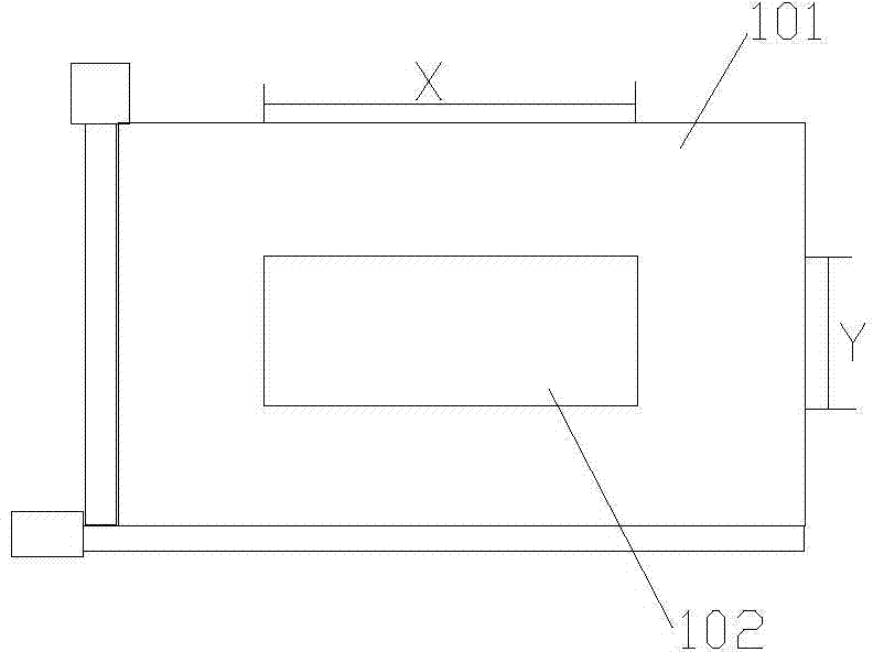
[0039]figure 1 The object table 101 and the working area 102 on the object table 101 are given in , and the slide glass is generally set in the working area. A light source is generally arranged below the working area 102 , and a lens is generally arranged above the working area 102 . The stage 101 can move along the plane defined by the X-axis and the Y-axis, and the working area 102 can also move correspondingly. The X-axis and Y-axis are established on the stage 101, and the Z-axis is perpendicular to the XY plane.

[0040] Introduce method of the present invention below:

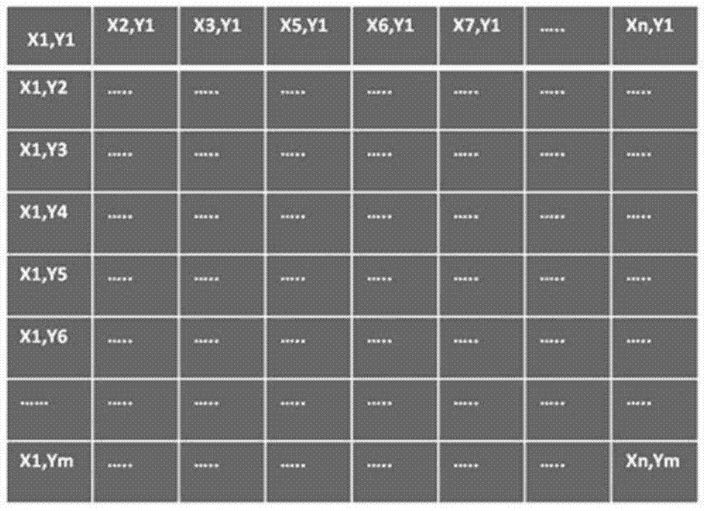
[0041] A. Divide the working area 102 of the stage 101 into n scanning points along the X-axis and the Y-axis to form a scanning coordinate system Sn(x, y), such as figure 2 As shown, each scan point corresponds to a coordinate, such as S1(x1,y1), S2(x2,y1) and so on....


PUM


Abstract

The invention discloses a micro-scanning platform, a shooting method and a work area flatness calibration method. Continuous scanning on a low precision platform can be achieved. The method mainly comprises the steps that a scanning coordinate system is set up in a work area; through a plane formula A1X+B1Y+C1Z+D1=0 and a standard slide, the calibration values En of the flatnesses of all scanning points in the work area of an objective table are determined; then, in actual sample slide shooting, the actual focusing position of each scanning point is determined according to the corresponding En. In this way, all scanning points can be adjusted to be in place before a camera shoots all the scanning points. The continuous scanning on the low precision platform can be achieved. Moreover, the scanning precision is high, scanning efficiency is high, and shot photos are clear. Due to the fact that high-precision continuous scanning is achieved on the low precision platform, the manufacturing cost of a high-precision scanning device is remarkably reduced.

Description

technical field [0001] The invention relates to the field of continuous scanning of microscopes, in particular to a microscopic scanning platform, a photographing method and a method for calibrating the flatness of a working area. Background technique [0002] Microscope is a common tool for observing the microscopic world, and is currently widely used in biomedical diagnostic research and industrial production. At present, automatic microscopes are more and more widely used, that is, the movement of the slide on the stage, the focus between the lens and the sample, and the shooting of the sample image are all driven by the automated XY-axis stage, Z-axis lens drive and digital microscope. Camera linkage is complete. [0003] Usually, samples for microscope observation are placed on a glass slide (25mm x 75mm), placed on the working area of ​​the stage, and then illuminated by transmitted light (mostly biological samples) or placed directly on the stage for illumination by ...

Claims


Application Information

Patent Timeline
IPC IPC(8): G02B21/36
CPCG02B21/36G02B21/365
Inventor 殷跃锋
Owner SUZHOU CHUANGJI BIOLOGICAL TECH
Why Eureka
Try Eureka