Dual-color surface plasmon beam splitter of asymmetrical nanometer groove structure and beam splitting method

A surface plasmon and beam splitter technology, applied in the field of nanophotonics, can solve the problems of increasing the size of the SPPs beam splitter, low beam splitting ratio, and shortening the transmission distance of SPPs

Inactive Publication Date: 2015-06-24
PEKING UNIV
View PDF1 Cites 3 Cited by
  • Summary
  • Abstract
  • Description
  • Claims
  • Application Information

AI Technical Summary

Problems solved by technology

However, these additional grating structures greatly increase the size of the SPPs beam splitter, which is not conducive to high integration
Furthermore, the beam splitting of SPPs can also be realized by covering a layer of dielectric film with a finite thickness on the asymmetric nanometer single slit, but due to the increase of the dielectric film, the transmission distance of SPPs is shortened, and at the same time, the device design and processing costs are reduced. flexibility
In addition, due to the limitation of the low transmittance of nano-single slits, the efficiency of excitation of SPPs by this kind of two-color surface plasmon beam splitter based on nano-single-slit structure is relatively low, which greatly limits its practical application.
Recently, it was proposed to use the different reflective properties of nanogrooves with different sizes to SPPs, that is, to prepare a pair of parallel nanogrooves with different widths to realize submicron beam splitters, but the beam splitting ratio is too low. Only beam splitting ratios of 3:1 and 1:2 are obtained at 650nm and 750nm respectively

Method used


Image

  • Dual-color surface plasmon beam splitter of asymmetrical nanometer groove structure and beam splitting method
  • Dual-color surface plasmon beam splitter of asymmetrical nanometer groove structure and beam splitting method
  • Dual-color surface plasmon beam splitter of asymmetrical nanometer groove structure and beam splitting method

Examples


Embodiment Construction

[0031] The present invention will be further described through the embodiments below in conjunction with the accompanying drawings.

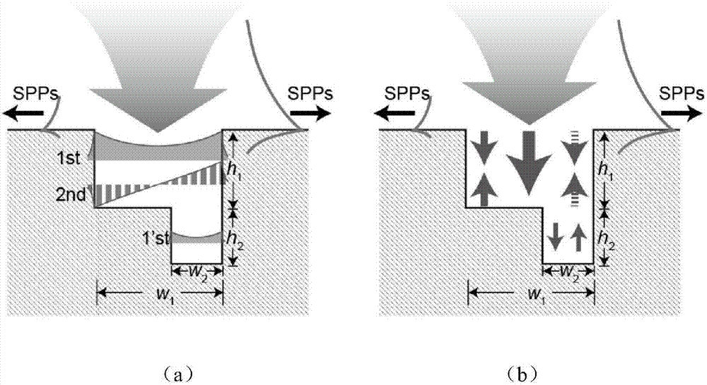
[0032] like figure 1 As shown, the two-color surface plasmon beam splitter based on the asymmetric nano-groove structure of this embodiment includes: a metal film; a wide main nano-groove is arranged on the surface of the metal film; The right side is provided with a narrow additional nanotrench, forming an asymmetric nanotrench structure. The widths of the main nanotrench and the additional nanotrench are w 1 and w 2 , the depth is h 1 and h 2 . lambda 1 is the first working wavelength, w 1 at 0.4λ 1 ~0.9λ 1 between to ensure that only the first-order waveguide mode 1st and the second-order waveguide mode 2nd are propagating modes in the main nanotrench at the first working wavelength; w 2 at 0.05λ 1 ~0.3λ 1 , to ensure that only the first-order waveguide mode 1'st is the propagating mode in the additional nanotrench at the first op...


PUM


Abstract

The invention discloses a dual-color surface plasmon beam splitter of an asymmetrical nanometer groove structure and a beam splitting method. The dual-color surface plasmon beam splitter comprises a metal thin film. A main nanometer groove is formed in the surface of the metal thin film, an additional nanometer groove is formed in one side of the bottom of the main nanometer groove, and then the asymmetrical nanometer groove structure is formed. Through the depths of the main nanometer groove and the additional nanometer groove in a control structure, the relative amplitude and phase differences of excited SPPs are regulated and controlled, the one-way excitation of the SPPs in one direction is achieved under the first working wavelength, the contribution to the SPPs excited in a third-order wave guide mode is further made, and the one-way excitation of the SPPs in the opposite direction is achieved under the shorter second working wavelength. The beam splitter has the high SPPs excitation efficiency, the high extinction ratio and other high performance at the same time; due to the super-small size of hundreds of nanometers, highly integration is facilitated, and therefore the beam splitter is widely applied to an ultrahigh integrity SPPs photonic circuit.

Description

technical field [0001] The invention relates to the field of nanophotonics, in particular to a two-color surface plasmon beam splitter based on an asymmetric nano-groove structure and a beam splitting method thereof. Background technique [0002] Surface plasmon polaritons (Surface Plasmon Polaritons) SPPs are currently a hot spot in nanophotonics research. The surface plasmon is a collective oscillation that exists at the interface between the metal and the medium coupled with the light wave and the free electrons in the metal. It is a special electromagnetic field in the interface bound mode. Its existence can be solved by solving the interface between the metal and the medium. It is obtained from Maxwell's equations under the boundary conditions. The biggest feature of SPPs is that they can localize the light field within the sub-wavelength size at the interface between the metal and the medium, breaking through the diffraction limit of traditional optics. At the same ti...

Claims


Application Information

Patent Timeline
Patent Type & Authority Applications(China)
IPC IPC(8): H01S4/00G02B6/122B82Y20/00
Inventor 廖慧敏李智姚文杰刘尚孙成伟陈建军龚旗煌
Owner PEKING UNIV
Why Eureka
Try Eureka