High-temperature superconductive flywheel energy storage system based on permanent magnetic drive

A high-temperature superconducting and flywheel energy storage technology, applied in the field of high-temperature superconducting flywheel energy storage systems, can solve the problems of reduced efficiency, consumption, and increased operating costs, and achieve the effects of improving efficiency, improving system efficiency, and compact structure

Inactive Publication Date: 2015-06-24
INST OF ELECTRICAL ENG CHINESE ACAD OF SCI
View PDF6 Cites 11 Cited by
  • Summary
  • Abstract
  • Description
  • Claims
  • Application Information

AI Technical Summary

Problems solved by technology

This structure has the following problems: (1) The motor is set on the main shaft of the flywheel. The defect of this structure is that when the flywheel is storing energy, the motor rotor rotates with the flywheel to consume energy, that is, the no-load loss of the motor becomes the main source of rotation loss One; (2) The motor is built in a vacuum chamber, and the stator winding produces a lot of heat loss when the motor is running. Most companies or research institutions use the motor stator liquid cooling method to dissipate heat, that is, a liquid pump is required for long-term work
This reduces the efficiency of the entire system and greatly increases operating costs

Method used


Image

  • High-temperature superconductive flywheel energy storage system based on permanent magnetic drive
  • High-temperature superconductive flywheel energy storage system based on permanent magnetic drive
  • High-temperature superconductive flywheel energy storage system based on permanent magnetic drive

Examples


Embodiment Construction

[0027] The present invention will be further described below in conjunction with the accompanying drawings and specific embodiments.

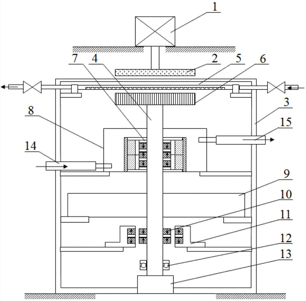
[0028]figure 1 It is a structural schematic diagram of a permanent magnet-driven radial high-temperature superconducting flywheel energy storage system according to Embodiment 1 of the present invention. Such as figure 1 As shown, the permanent magnet-driven radial high-temperature superconducting flywheel energy storage system consists of a driving part, a superconducting magnetic shielding mechanism 5 and an energy storage part. The drive part, the superconducting magnetic shielding mechanism 5 and the energy storage part are sequentially arranged up and down along the axial direction. The driving part is located above the superconducting magnetic shielding mechanism 5, and the superconducting magnetic shielding mechanism 5 is located axially above the energy storage part. The superconducting magnetic shielding mechanism 5 and the energy st...


PUM


Abstract

A high-temperature superconductive flywheel energy storage system based on permanent magnetic drive comprises a drive part, a superconductive magnetic shielding mechanism and an energy storage part. The drive part, the superconductive magnetic shielding mechanism and the energy storage part are vertically and sequentially arranged in the axial direction. The superconductive magnetic shielding mechanism and the energy storage part are located in a seal cavity (3), the drive part is located outside the seal cavity (3), and the energy storage part is isolated from the drive part. The seal cavity (3) can provide a vacuum environment for the energy storage part. The drive part provides energy for the energy storage part. The superconductive magnetic shielding mechanism is a switch starting or stopping energy input and enabling magnetic field coupling between a permanent magnet disc of the drive part and a metal disc of the energy storage part to be communicated or separated. The end face of the superconductive magnetic shielding mechanism keeps parallel and coaxial with the end face of the permanent magnet disc of the drive part and the metal disc of the energy storage part. The energy storage part stores energy transmitted by the drive part, and a high-temperature superconductive bearing of the energy storage part comprises a permanent magnet rotor and a superconductive stator.

Description

technical field [0001] The invention relates to a high-temperature superconducting flywheel energy storage system, in particular to a high-temperature superconducting flywheel energy storage system driven by permanent magnets. Background technique [0002] Flywheel energy storage system (FESS) is an efficient, clean and environment-friendly energy system. Its working principle is: when the motor drives the flywheel rotor to rotate at high speed in the form of a motor, the electrical energy is converted into kinetic energy and stored in the flywheel; when the motor operates as a generator, the kinetic energy stored in the flywheel is converted into electrical energy and released. With the development of superconducting technology, high temperature superconducting flywheel energy storage system (SFESS) appeared. It adopts high-temperature superconducting magnetic suspension bearings to make the flywheel rotor achieve stable suspension, thereby greatly reducing the rotational ...

Claims


Application Information

Patent Timeline
Patent Type & Authority Applications(China)
IPC IPC(8): H02K7/02H02K7/09
CPCY02E60/16H02K7/025H02K7/09
Inventor 张国民余志强李万杰邱清泉王全胜胡磊肖立业林良真
Owner INST OF ELECTRICAL ENG CHINESE ACAD OF SCI
Why Eureka
Try Eureka