

Axial-field permanent magnet compensated impulse generator with double contra-rotating rotors
An axial magnetic field and compensation pulse technology, applied in electrical components, electromechanical devices, etc., can solve the problems of parallel current synchronization, increase system volume, double switch control devices, etc., to reduce torque impact, reduce system volume and size effect with weight reduction
- Summary
- Abstract
- Description
- Claims
- Application Information
AI Technical Summary
Problems solved by technology
Method used
Image

Examples
specific Embodiment approach 1
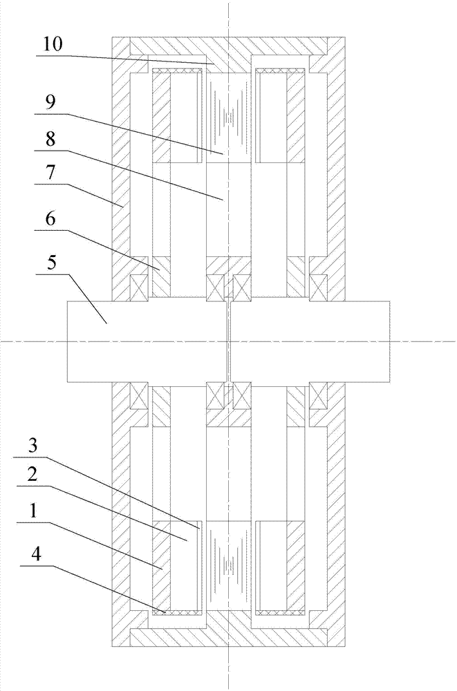
[0024] Specific implementation mode one: the following combination figure 1 Describe this embodiment, the axial magnetic field permanent magnet counter-rotating dual-rotor compensation pulse generator described in this embodiment includes a left rotor, a stator disk, a right rotor, two end covers 7 and a casing 10,
[0025] The left rotor, the stator disc and the right rotor are sequentially arranged in the cylindrical space formed by the two end covers 7 and the casing 10 in the axial direction, and the left rotor and one end cover 7 are connected with the right rotor and the other end cover. 7. The two sides of the stator disk are symmetrically distributed in a mirror image; an air gap is formed between the left rotor and the stator disk, and an air gap is formed between the stator disk and the right rotor;
[0026] The left rotor includes a left rotor disc yoke 1, a left rotor permanent magnet 2, a left rotor compensating disc 3, a left rotor bandage 4, a left rotor shaft 5...
specific Embodiment approach 2
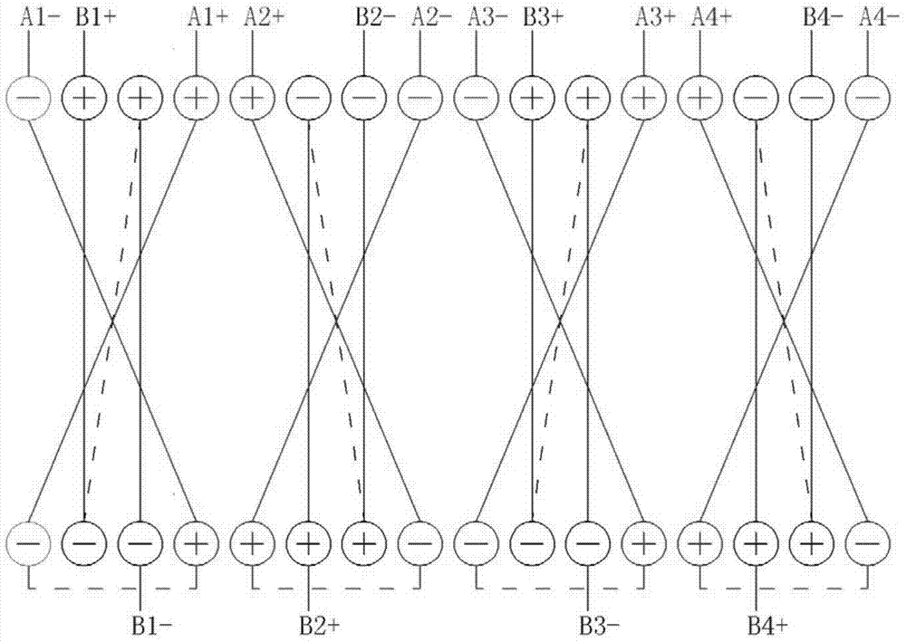
[0037] Embodiment 2: In this embodiment, Embodiment 1 is further described. The stator armature winding is a ring winding structure, and there are two phase windings in total, and each phase winding includes four coils.
specific Embodiment approach 3
[0038] Specific implementation mode three: the following combination figure 2 Describe this embodiment, this embodiment will further explain Embodiment 2, the two-phase windings of the stator armature windings are A-phase windings and B-phase windings, and the A-phase windings are composed of four windings A1, A2, A3 and A4. Phase B winding consists of four coils B1, B2, B3 and B4, A1 and B1 coils, A2 and B2 coils, A3 and B3 coils, A4 and B4 coils form four coil groups one by one. The four coil groups are evenly distributed on the inner and outer wall surfaces of the stator disk yoke 9 along the circumferential direction of the stator disk yoke 9, and the four coil groups are wound in the same axial direction on the side walls of the stator disk yoke 9;
[0039] For the A1 and B1 coils, the A1 and B1 coils are respectively located in the coil sides on the inner and outer walls of the stator yoke 9, the coil side of the B1 coil is in the center, the coil sides of the A1 coil a...
PUM
 Abstract
Description
Claims
Application Information