A low-frequency permanent magnet vibration generator

A vibrating generator and permanent magnet technology, applied to electrical components, electromechanical devices, etc., to achieve the effects of reducing magnetic flux leakage, facilitating assembly, and improving utilization

Inactive Publication Date: 2017-03-01
HEBEI UNIV OF TECH
View PDF1 Cites 0 Cited by
  • Summary
  • Abstract
  • Description
  • Claims
  • Application Information

AI Technical Summary

Problems solved by technology

[0005] Aiming at the problems existing in existing vibration generators, a low-frequency permanent magnet vibration generator is designed considering the vibration under the condition of low frequency and large displacement

Method used


Image

  • A low-frequency permanent magnet vibration generator
  • A low-frequency permanent magnet vibration generator
  • A low-frequency permanent magnet vibration generator

Examples


Embodiment 1

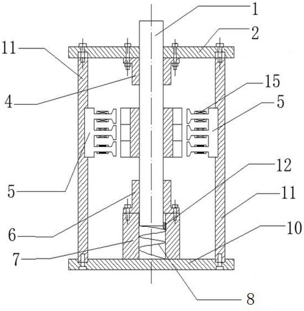
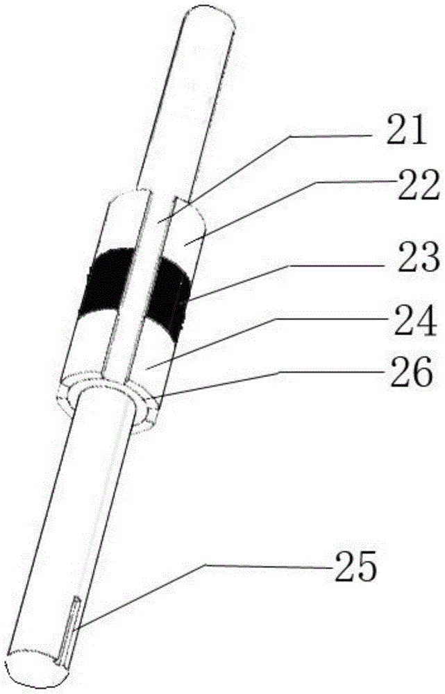
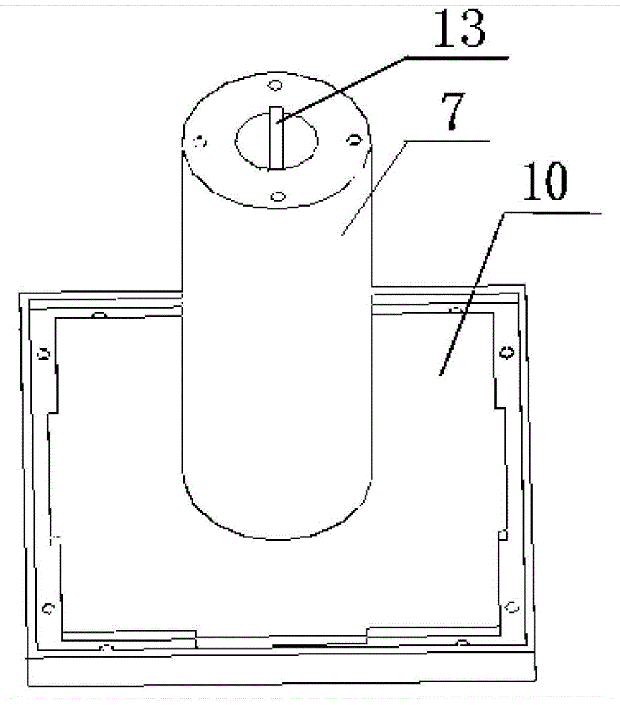
[0040] This embodiment adopts the above-mentioned connection method, the upper end cover and the lower end cover are cuboid plates with square grooves on the edges, and the grooves of the upper and lower end covers are used for embedding four side plates. Vibration shaft part: Use cylindrical austenitic stainless steel (non-magnetic material) as the vibration shaft 1 to avoid affecting the magnetic circuit. The total length of the vibrating shaft is 890mm, the diameter at both ends is 25mm, the installation length of the middle part of the silicon steel sheet of the moving element is 150mm, and the ring diameter is 10mm, and there are four 5mm deep moving silicon steel sheet grooves with an arc of 60° evenly around it. 26. The length of the vibration axis at the upper end of the mover silicon steel sheet 21 is 370 mm, and the length of the vibration axis at the lower end of the mover silicon steel sheet is 370 mm. Each mover silicon steel sheet groove 26 respectively places th...

Embodiment 2

[0043] In the present embodiment, the vibration axis 1 is a 25mm cylindrical stainless steel, and the concave part of the silicon steel sheet in the middle is equipped with arc-shaped magnetic tile NdFeB permanent magnets 22-24 (Nd2Fe14B, model N45), and the three permanent magnets are vertically attached together. Polarity is reversed successively, a week altogether four groups, end has 3.5 * 4 * 8mm square keyway 25.

[0044] Considering the strong attraction between the permanent magnet and the yoke, the circular flange linear bearings (upper flange bearing 4 and lower flange bearing 6) distributed at both ends are used to limit the vibration axis, and the permanent magnet and the yoke The gravitational force between the yokes is converted into the rolling friction force between the vibrating shaft and the bearing, which greatly reduces the influence of the magnetic force on the vibration of the generator.

[0045] Figure 5 It is the waveform diagram of the output electro...

Embodiment 3

[0047] In this embodiment, the above-mentioned connection method is adopted, and the upper end cover and the lower end cover are tightly and fixedly connected with the four side plates through mutually matching mortise joint structures. The generator can output relatively large output voltage when the vibration frequency is 1-5Hz and the vibration displacement peak value is 100-200mm.


PUM


Abstract

The invention relates to a low-frequency permanent magnet vibration generator. The low-frequency permanent magnet vibration generator is characterized in that a main body structure of the generator is a regularly quadrangular prism, the generator comprises four side plates, an upper end cap and a lower end cap, the four side plates are fixedly connected with the upper end cap and the lower end cap, a hole is formed in the middle of the upper end cap, a hollow cylindrical hub is arranged on the upper portion of the lower end cap, a spring is placed in a hollow portion of the bottom in the hub, a lower flange bearing of which the inner diameter is the same with the diameter of a vibrating shaft is arranged on the top of the hub and is fixedly connected with the top of the hollow cylindrical hub through a bolt, the lower portion of the vibrating shaft penetrates in the lower flange bearing and is in contact with the spring in the hub, and the upper end of the vibrating shaft penetrates in the upper flange bearing and the upper end cap fixed with the upper flange bearing, and is higher than the upper end cap. Under the excitation effect of sinusoidal vibration of which the vibration frequency is 1.25 Hz and the peak value is 150mm, an outgoing line of a coil on each side plate can be vibrated to generate an induced electromotive force of which the peak value is 30V, and the vibration generator has the considerable outputting voltage at low frequency.

Description

technical field [0001] The invention relates to a device for converting vibrational mechanical energy into electric energy, in particular to a permanent magnet vibration power generation device. The core part is a permanent magnet vibration shaft, a magnetic yoke, a hub and a regular square prism shell. The vibrating generator can form a closed magnetic circuit, significantly reduce leakage magnetic flux, and has higher output power at low frequency. Background technique [0002] The permanent magnet vibration generator is a power generation device that converts environmental vibration energy into electrical energy by using the law of electromagnetic induction. It has the advantages of large power generation and easy maintenance. [0003] According to the different vibrating parts, permanent magnet vibration generators can be divided into three types: moving iron (magnet movement), moving coil (coil movement) and iron ring co-movement (magnet and coil movement together). Th...

Claims


Application Information

Patent Timeline
IPC IPC(8): H02K35/02
Inventor 王博文李恒王志华赵智忠曹淑瑛
Owner HEBEI UNIV OF TECH
Why Eureka
Try Eureka