Boost unit Z-source inverter

A source inverter and inverter bridge technology, applied in the field of power electronic converters, can solve the problems of small turn ratio, high-frequency transformer boost volume, large weight loss, etc., and achieve high boost characteristics and wide input voltage range , the effect of high conversion efficiency

Inactive Publication Date: 2015-06-24
NANJING UNIV OF AERONAUTICS & ASTRONAUTICS
View PDF5 Cites 15 Cited by
  • Summary
  • Abstract
  • Description
  • Claims
  • Application Information

AI Technical Summary

Problems solved by technology

[0005] The purpose of the present invention is to provide a boost unit Z-source inverter with small turn ratio, wider input voltage range, and good boost characteristics, which solves the problems of high-frequency transformer boost volume, weight, and large loss

Method used


Image

  • Boost unit Z-source inverter
  • Boost unit Z-source inverter
  • Boost unit Z-source inverter

Examples


Embodiment 1

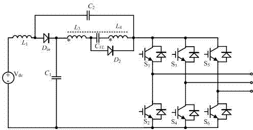
[0032] Such as figure 1 The Z-source inverter of the boost unit includes a Z-source structure, a boost unit and an inverter bridge. The input terminal of the Z-source inverter of the boost unit is connected to a DC voltage source, and the output terminal is connected to a filter inductor and a filter capacitor. In this embodiment, the second inductor in the conventional Z-source structure is replaced by a boost unit.

[0033] Specifically, the Z source structure provided by this embodiment includes: DC voltage source V dc , the first inductance L 1 , boost unit, first capacitor C 1 , the second capacitance C 2 and the first power diode D in ; Among them: the first inductance L 1 One end of the DC voltage source is connected to the positive pole, and the first inductor L 1 The other end of the first power diode D in the anode and the second capacitor C 2 One end of the connection; the first power diode D in The cathode is connected to one end of the boost unit and the ...

Embodiment 2

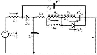
[0058] Such as Figure 8 The boost unit Z-source inverter shown is another embodiment provided by the present invention, which includes a Z-source structure, a boost unit and an inverter bridge. The Z-source structure includes two sets of capacitors, two sets of inductors, a boost unit and a power diode connected across the midpoint of the two sets of inductors and capacitors. The above boost unit includes a coupling inductor, a capacitor and a power diode. The coupled inductor includes a first winding and a second winding, and the output voltage gain is determined by setting the turn ratio of the second winding to the first winding. In this embodiment, the second inductor in the conventional Z-source structure is replaced by a boost unit.

[0059] Specifically, the Z source structure provided by this embodiment includes: DC voltage source V dc , the first inductance L 1 , boost unit, first capacitor C 1 , the second capacitance C 2 and the first power diode D in ; Amon...

Embodiment 3

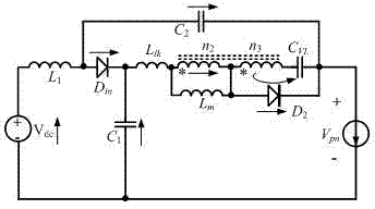
[0064] Such as Figure 9 The boost unit Z-source inverter shown includes a Z-source structure, a boost unit and an inverter bridge. The Z source structure includes two sets of capacitors, two sets of inductors, a boost unit, a DC voltage source connected across the midpoint of the two sets of inductors and capacitors, and a power diode. The boost unit includes a coupled inductor, a capacitor, and a power diode. The coupled inductor includes a first winding and a second winding. The output voltage gain is determined by setting the turn ratio of the second winding to the first winding.

[0065] Specifically, the Z source structure provided by this embodiment includes: DC voltage source V dc , the first inductance L 1 , the second inductance L 2 , the first capacitance C 1 , the second capacitance C 2 and the first power diode D in ; Among them: the first inductance L 1 One end of the first capacitor C 1 One end of the inverter bridge is connected to the negative end, the...


PUM


Abstract

The invention discloses a boost unit Z-source inverter. A boost unit is arranged in a Z-source structure and comprises a coupling inductor, a third capacitor and a second power diode, the coupling inductor comprises a first winding and a second winding which are connected in series in the forward direction, the unlike end of the first winding is connected with one end of the third capacitor and the positive pole of the second power diode, the dotted terminal of the second winding is connected with the other end of the third capacitor, and the unlike end of the second winding is connected with the negative pole of the second power diode. Compared with a traditional quasi-Z-source inverter, the input voltage range is wider, conversion efficiency is higher, and higher boost characteristic is achieved during low-voltage input.

Description

technical field [0001] The invention relates to a boost unit Z-source inverter, which belongs to the field of power electronic converters. Background technique [0002] Inverters are widely used in motor drives, uninterruptible power supplies, static var generators and compensators, and active filtering. The traditional inverter circuit generally has a two-stage structure, the front stage is a direct-to-direct step-up converter, and the rear stage is an inverter. In the two-stage structure, the DC link needs to be added with decoupling capacitors, which has a large volume and weight. The front and back stages are controlled separately, resulting in a complex overall structure and cumbersome control of the traditional inverter structure. [0003] In order to solve the above problems of traditional inverters, some scholars have proposed the concept of Z-source inverters. The Z-source inverter is a single-stage buck-boost inverter. It couples the DC source with the inverter s...

Claims


Application Information

Patent Timeline
Patent Type & Authority Applications(China)
IPC IPC(8): H02M7/48
Inventor 汤雨李林林
Owner NANJING UNIV OF AERONAUTICS & ASTRONAUTICS
Why Eureka
Try Eureka