Optical fiber monitoring system and monitoring method for free switching of three working modes

A monitoring system and working mode technology, applied in transmission systems, digital transmission systems, electromagnetic wave transmission systems, etc., can solve problems such as wasting labor, data loss, and inability to realize free switching, and achieve the effect of solving data loss

Inactive Publication Date: 2017-05-17
国网吉林省电力有限公司信息通信公司
View PDF12 Cites 0 Cited by
  • Summary
  • Abstract
  • Description
  • Claims
  • Application Information

AI Technical Summary

Problems solved by technology

[0004] The present invention provides an optical fiber monitoring system with three working modes for free switching in order to solve the problems of wasting manpower and untimely switching in the existing optical fiber monitoring equipment, resulting in data loss and the inability to realize free switching.

Method used


Image

  • Optical fiber monitoring system and monitoring method for free switching of three working modes
  • Optical fiber monitoring system and monitoring method for free switching of three working modes

Examples


specific Embodiment approach 1

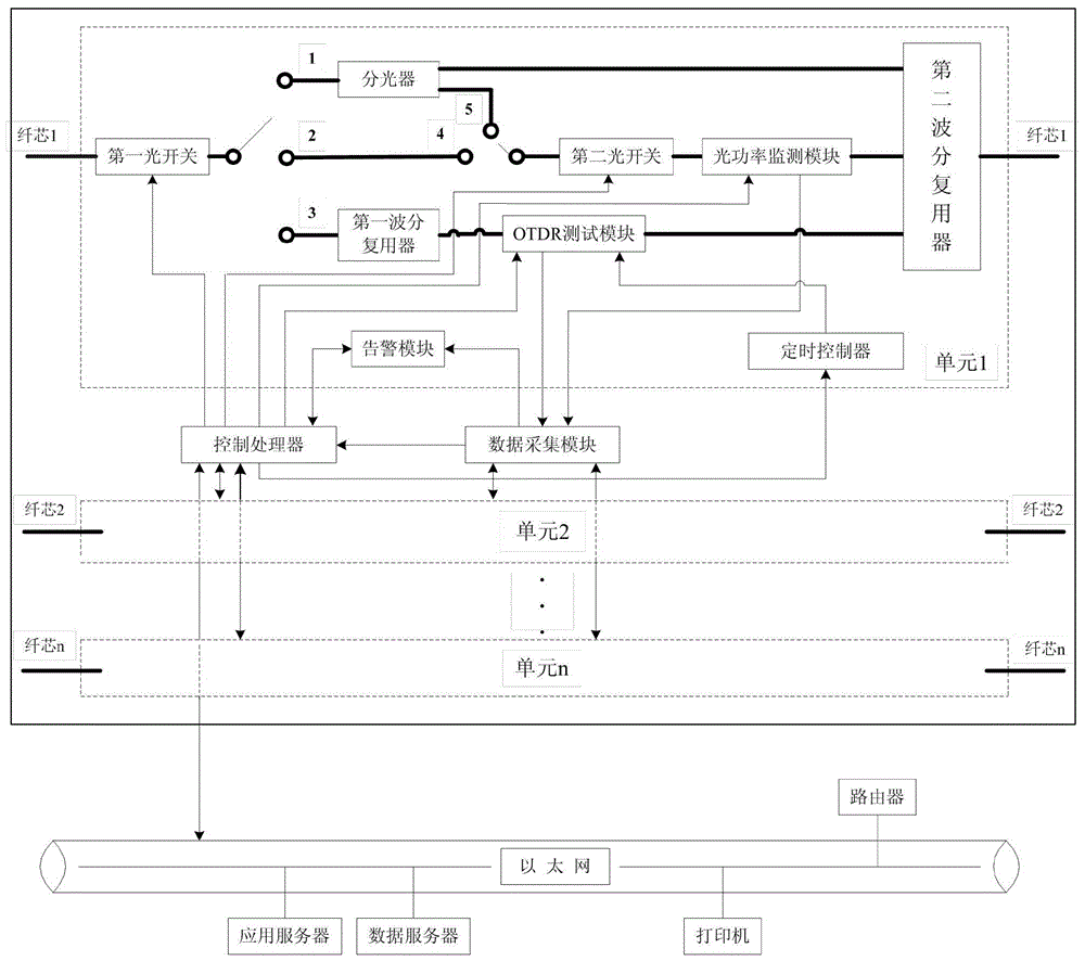
[0014] Specific implementation mode 1. Combination figure 1 with figure 2 Describe this embodiment mode, the optical fiber monitoring system of three kinds of operating modes free switching, comprise one or more monitoring units, each monitoring unit comprises control processor, data acquisition module, timing controller, optical power monitoring module, OTDR test module, An alarm module, two optical switches, a first wavelength division multiplexer, a second wavelength division multiplexer and an optical splitter. in:

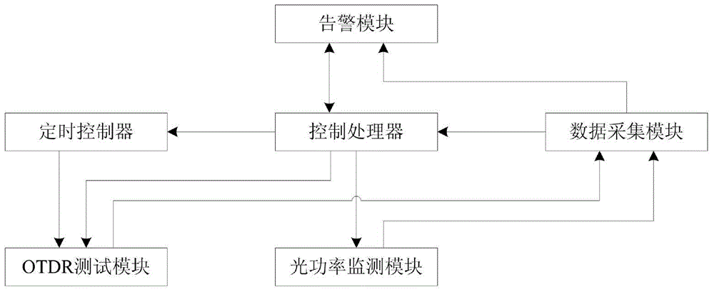
[0015] The control processor is respectively connected with the optical power monitoring module, OTDR test module, data acquisition module, alarm module, timing controller, first optical switch, and second optical switch through the electrical interface to realize the control of each sub-module, and then through the RJ45 The network port is connected to the Ethernet and connected to the application server and data server to realize remote control; the data ...

specific Embodiment approach 2

[0018] Specific embodiment two, combine figure 1 with figure 2 This embodiment is described. This embodiment is the monitoring method of the optical fiber monitoring system with free switching of the three working modes described in the first specific embodiment. figure 1 In , the thick black connection line represents the fiber core and optical path, and the thin black connection line represents the data connection. The system consists of multiple monitoring units, each monitoring unit includes: control processor, data acquisition module, timing controller, optical power monitoring module, OTDR test module, alarm module, first optical switch, second optical switch, second A wavelength division multiplexer, a second wavelength division multiplexer and an optical splitter. Unit 1, unit 2...unit n share the control processor and data acquisition module, and each unit can realize the monitoring function of three working modes for one optical fiber.

[0019] The application se...


PUM


Abstract

The invention provides an optic fiber monitoring system and monitoring method switching three operation modes freely, relates to the field of power system optic fiber communication and solves the problems that according to an existing optic fiber monitoring device, labor force is wasted, data loss since switching cannot be performed timely and switching cannot be implemented freely. A control processor is connected to an optic power monitoring module, an OTDR testing module, a data acquisition module, an alarming module, a timing controller, a first optic switch and a second optic switch; the control process is assessed with Ethernet through a network interface RJ45 and is connected to an application server and a data server; the data acquisition module is connected to the OTDR testing module and the optic power monitoring module; the timing controller is connected to the OTDR testing module; the optic power monitoring module is connected to the second optic switch; the OTDR testing module is connected to two multiplexers; the alarming module is connected to the data acquisition module. The system is capable of switching three operation modes of operation fibers, bright auxiliary fibers and dull auxiliary fibers freely.

Description

technical field [0001] The invention relates to the field of optical fiber communication in electric power systems, in particular to an optical fiber monitoring system with free switching of three working modes. Background technique [0002] In communication systems, optical fiber communication is a very important communication method. In practical applications, with the continuous development of optical fiber communication technology, due to the advantages of optical fiber with large capacity, high transmission information quality, long transmission distance, stable performance, strong anti-electromagnetic interference, and strong corrosion resistance, it is widely used in power system communication. The application is more and more extensive. [0003] But at the same time, the maintenance and management problems of optical fiber lines are becoming more and more prominent. The number of various new equipment, new systems, and new technologies used in optical fiber communi...

Claims


Application Information

Patent Timeline
Patent Type & Authority Patents(China)
IPC IPC(8): H04B10/071H04B10/077H04B10/032H04L12/24
Inventor 隋吉生陈晓娟姜万昌赵亮王圣达郑国男马冬梅王林武迪郭健
Owner 国网吉林省电力有限公司信息通信公司
Why Eureka
Try Eureka