Supercharge Your Innovation With Domain-Expert AI Agents!

High-stability mini-tiller

A micro-tiller, smooth technology, applied in the field of micro-tiller, can solve the problems of start-up failure, heavy weight, laborious shifting, etc., to reduce labor intensity, ensure successful start-up, and avoid start-up failure

Inactive Publication Date: 2015-07-01
重庆市家创扬帆科技有限公司
View PDF0 Cites 4 Cited by
  • Summary
  • Abstract
  • Description
  • Claims
  • Application Information

AI Technical Summary

Problems solved by technology

[0002] The existing micro-tillers currently include 178 / 186 direct-coupled micro-tillers and 80 / 90 belt chain micro-tillers. The 178 / 186 type has high transmission efficiency, but it is bulky, heavy, and laborious to shift gears; Although the cultivator is light in weight and small in size, its transmission efficiency is low, and the belt needs to be maintained. Both have their own advantages and disadvantages. The starter includes a handle, a cable, a turntable driven by the cable, and a return spring to reset the cable. Although this starting method can complete the start of the engine, it is difficult to start, and often fails to start due to different force conditions of the operator. In some cases, it is necessary to pull the cable several times to start, which is extremely labor-intensive and inconvenient to use

Method used


Image

  • High-stability mini-tiller
  • High-stability mini-tiller
  • High-stability mini-tiller

Examples


Embodiment Construction

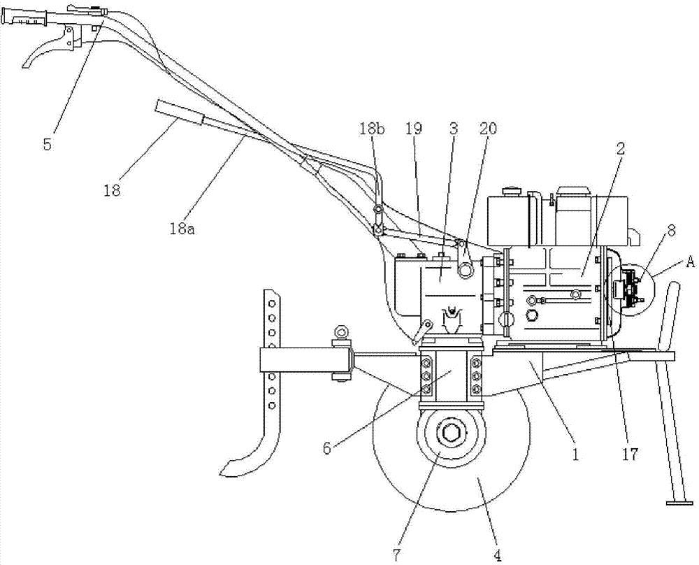
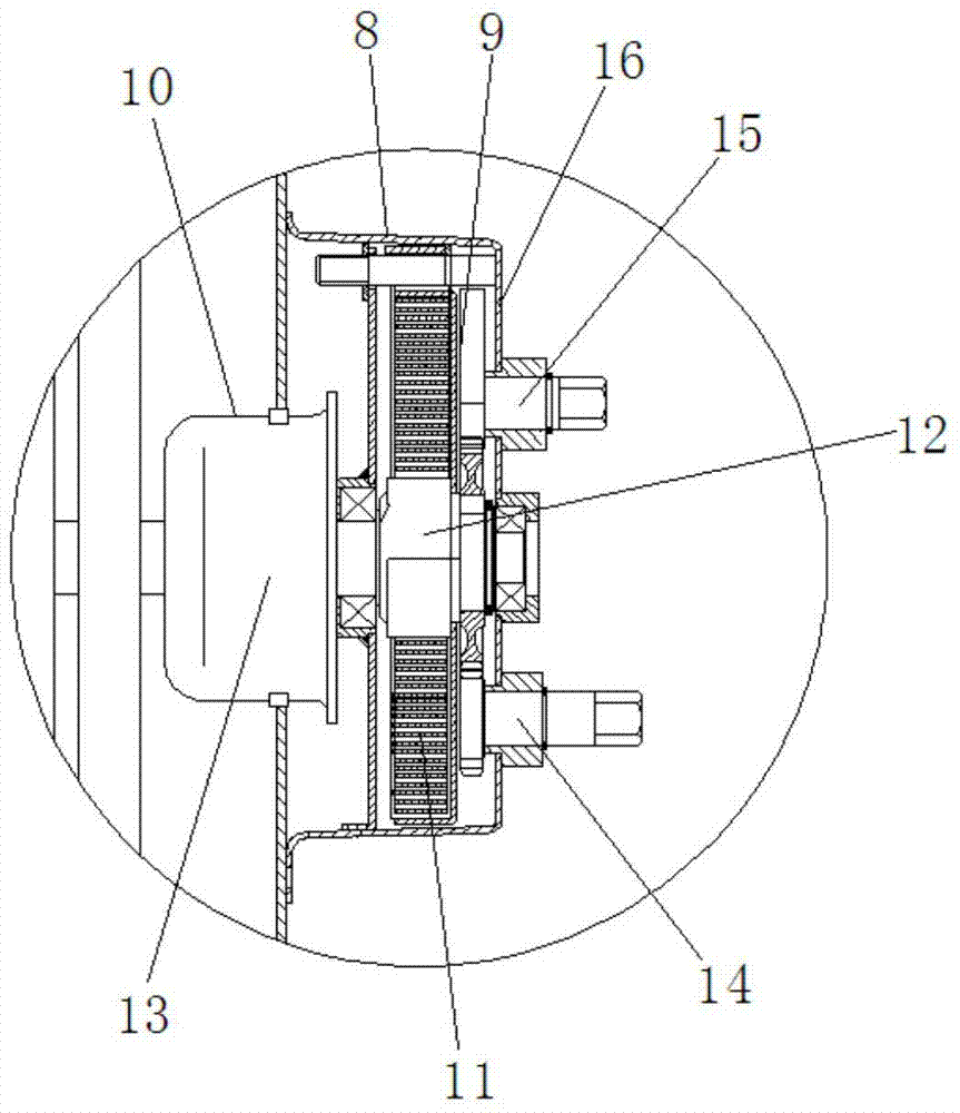
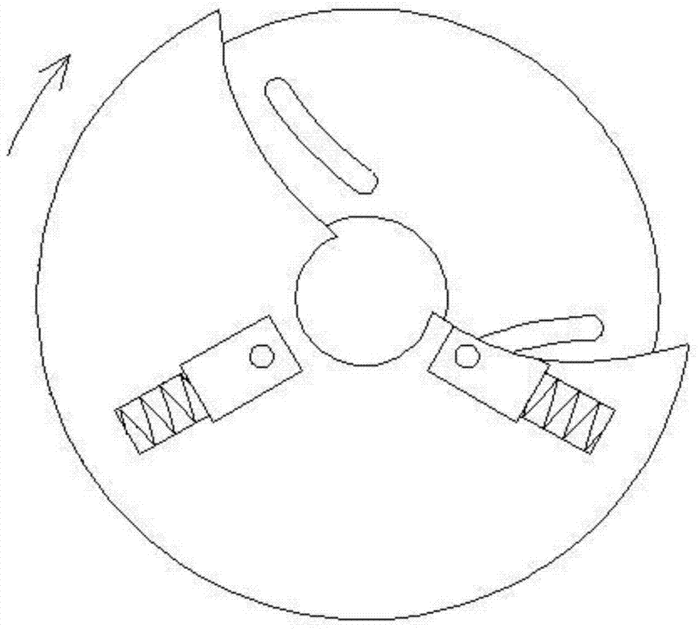
[0020] figure 1 It is a structural schematic diagram of the present invention, figure 2 for figure 1 The zoomed-in view at A, image 3 It is a schematic diagram of the flywheel structure, as shown in the figure: the high stability tillage machine of the present embodiment includes a frame 1, an engine 2, a gearbox 3, a walking wheel 4 and a control handle 5, and the engine 2 and the gearbox 3 are fixed Installed on the frame 1, a transmission box 6 and a travel box 7 are fixedly arranged under the gearbox 3 in sequence, and the wheel shaft of the travel wheel 4 is connected to the travel box 7 in a single degree of freedom rotation and passes through the transmission box 6. The transmission part is connected with the gearbox 3, the control handle 5 is fixedly mounted on the gearbox 3, and the engine 2 is provided with a starter 8 for driving its crankshaft to start; the starter 8 includes an energy storage device 9 and the energy conversion mechanism 10 connected to the cr...


PUM


Abstract

The invention discloses a high-stability mini-tiller which comprises a framework, an engine, a gearbox, traveling wheels and a control handle. The engine is provided with a starter, and the starter is used for driving a crankshaft of the engine to rotate, so that the engine can be started; the starter comprises an energy storage device and an energy conversion mechanism, and the energy conversion mechanism is in transmission connection with the crankshaft of the engine; energy can be provided for the energy conversion mechanism by the energy storage device and can be converted into kinetic energy for driving the engine to be started; a flywheel of the engine comprises a flywheel body, at least two sliders and an elastic component; the sliders are uniformly arranged around a rotary shaft of the flywheel body and are radially slidably connected to the flywheel body; the elastic component is arranged between the sliders and the flywheel body in a connected manner and is used for providing elastic centrifugal force for the sliders. The high-stability mini-tiller has the advantages that the energy can be stored and released by the energy storage device, so that the engine can be driven by the starter of the engine to be started, the labor intensity can be relieved for operators as compared with the traditional manual starter, the high-stability mini-tiller is convenient to operate and wide in benefited service population, and energy and labor can be saved; the starting energy for the high-stability mini-tiller can be directly provided by the energy storage device, accordingly, starting failures due to difference in force generation conditions of the operators can be prevented, and successful starting can be guaranteed.

Description

technical field [0001] The invention relates to a tiller, in particular to a tiller with high stability. Background technique [0002] The existing micro-tillers currently include 178 / 186 direct-coupled micro-tillers and 80 / 90 belt chain micro-tillers. The 178 / 186 type has high transmission efficiency, but it is bulky, heavy, and laborious to shift gears; Although the cultivator is light in weight and small in size, its transmission efficiency is low, and the belt needs to be maintained. Both have their own advantages and disadvantages. The starter includes a handle, a cable, a turntable driven by the cable, and a return spring that resets the cable. Although this starting method can complete the start of the engine, it is difficult to start, and often fails to start due to different force conditions of the operator. In some cases, it is necessary to pull the cable many times to start, which is extremely labor-intensive and inconvenient to use. [0003] Therefore, there is...

Claims


Application Information

Patent Timeline
IPC IPC(8): A01B71/00
Inventor 王佳川
Owner 重庆市家创扬帆科技有限公司
Features
  • R&D
  • Intellectual Property
  • Life Sciences
  • Materials
  • Tech Scout
  • Unparalleled Data Quality
  • Higher Quality Content
  • 60% Fewer Hallucinations
Learn More