Forming method of amorphous alloy

A technology of amorphous alloy and ingot casting, which is applied in the field of amorphous alloy forming, can solve the problems of reducing production efficiency and prolonging the casting cycle of amorphous alloy, and achieve the effects of improving production efficiency, good product quality, and reducing the time for vacuum acquisition

Active Publication Date: 2015-07-01
BYD CO LTD
View PDF6 Cites 7 Cited by
  • Summary
  • Abstract
  • Description
  • Claims
  • Application Information

AI Technical Summary

Problems solved by technology

For example, the vacuum pressure mentioned in US6021840 is 1000 μm Hg, so each casting cycle needs to spend a lot of vacuum time to establish a vacuum environment to achieve the above vacuum pressure, and then start the operation of heating, melting and die casting, which greatly prolongs the The casting cycle of amorphous alloy reduces the production efficiency

Method used


Image

  • Forming method of amorphous alloy
  • Forming method of amorphous alloy
  • Forming method of amorphous alloy

Examples


Embodiment 1

[0042] This example is used to illustrate the method for forming the amorphous alloy of the present invention.

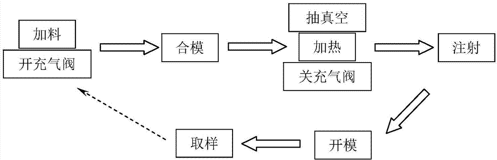
[0043] Use the die-casting machine disclosed in CN201231307, according to figure 1 The flow shown is for amorphous alloy forming.

[0044] Open the argon gas filling valve to fill the vacuum chamber and crucible with argon. After measurement, the oxygen content in the vacuum chamber is 6% by volume. Composition of ingredients as Zr 53 Al 10 Cu 30 Ni 7 The amorphous alloy ingot is fed into the crucible, and the mold is clamped at the same time. After keeping the vacuum chamber filled with argon for 2 seconds, start to heat the amorphous alloy ingot in the crucible by induction heating at a heating rate of 50°C / s. After 2 seconds from the start of heating, close the argon gas filling valve to stop filling with argon, and start to use a vacuum pump to evacuate at the same time, and simultaneously evacuate the mold and the injection channel. The pumping speed of ...

Embodiment 2

[0049] This example is used to illustrate the method for forming the amorphous alloy of the present invention.

[0050] Use the die-casting machine disclosed in CN201231307, according to figure 1 The flow shown is for amorphous alloy forming.

[0051] Open the argon filling valve to fill the vacuum chamber and crucible with argon, and make the composition into Ti 50 Ni 20 Cu 25 sn 5 The amorphous alloy ingot is fed into the crucible, and the mold is clamped at the same time. Start to heat the amorphous alloy ingot in the crucible by induction heating, and the heating rate is 50°C / s. After heating starts for 0 s, close the argon gas filling valve, and start vacuuming with the vacuum pump, simultaneously vacuuming the mold and the injection channel. The pumping speed of the vacuum pump can reduce the vacuum pressure of the vacuum chamber to below 1000Pa within 5 seconds. Vacuumize to reach a vacuum pressure of 1000Pa. Ti 50 Ni 20 Cu 25 sn 5 The melting point of the a...


PUM

PropertyMeasurementUnit
melting pointaaaaaaaaaa

Abstract

The invention discloses a forming method of amorphous alloy. The method includes: 1, under protection of inertial gas, heating an amorphous alloy ingot in a crucible in a vacuum chamber; 2, evacuating the vacuum chamber to obtain vacuum pressure of the vacuum chamber, being below 5000Pa, at the temperature lower than a melting point of the amorphous alloy ingot; 3, if the vacuum pressure is obtained in the step 2, continuing to heat the amorphous alloy ingot in the crucible until that the amorphous alloy ingot melts; 4, adding melt obtained in the step 3 under the vacuum condition, into a forming mold so as to obtain a formed amorphous alloy product. The forming method has the advantages that forming cycle can be shortened, production efficiency is improved and the formed amorphous alloy has good quality.

Description

technical field [0001] The invention relates to a method for forming an amorphous alloy. Background technique [0002] Since the amorphous alloy was first discovered in 1960, it has been a hot spot in the research of alloy materials. In the 1990s, the multi-element alloying method was adopted to reduce the critical cooling rate of amorphous alloys, realize the preparation of bulk amorphous alloys, and make the engineering application of such materials possible. Amorphous alloys have an atomic arrangement structure with short-range order and long-range disorder, which makes this type of material have excellent mechanical properties such as high strength, high elastic limit, and good wear resistance. [0003] Due to the formation of amorphous structure in the forming process of amorphous alloy, it is necessary to prevent the appearance of heterogeneous nucleation. However, the composition of amorphous alloy usually contains a variety of active elements, such as zirconium, alu...

Claims


Application Information

Patent Timeline
Patent Type & Authority Applications(China)
IPC IPC(8): B22D18/06B22D21/02
CPCB22D18/06B22D21/02
Inventor 李运春陈建新张法亮
Owner BYD CO LTD
Why Eureka
Try Eureka