Stirling engine and cup cover and cup with same

A Stirling engine and cup cover technology, which is applied in the field of cup covers and cups, can solve the problems of poor symmetry of the Stirling engine, high height of the Stirling engine, and design limitations of hot cylinder parameters, etc., and achieve good market prospects and rich Structural type, the effect of facilitating reasonable arrangement

Inactive Publication Date: 2015-07-01
NINGBO XIAYUAN TECH +1
View PDF3 Cites 9 Cited by
  • Summary
  • Abstract
  • Description
  • Claims
  • Application Information

AI Technical Summary

Problems solved by technology

[0003] However, the flywheels of the above-mentioned Stirling engines are all set perpendicular to the direction of motion of the power piston. This setting will cause the height of the overall Stirling engine to be too high. In some occasions that limit the overall height of the Stirling engine, the parameters of the upper part of the hot cylinder design is often limited
In addition, the flywheel generally needs to be supported by an independent bracket, which makes the overall complex, heavy, and costly, and the brackets are generally set eccentrically, resulting in poor symmetry of the Stirling engine, so there is a shortcoming of insufficient overall aesthetics
[0004] Furthermore, there is no special cup with a Stirling engine on the market so far, and the fun of the Stirling engine can be experienced while drinking tea, so it is necessary to carry out research and development.

Method used


Image

  • Stirling engine and cup cover and cup with same
  • Stirling engine and cup cover and cup with same
  • Stirling engine and cup cover and cup with same

Examples


Embodiment 1

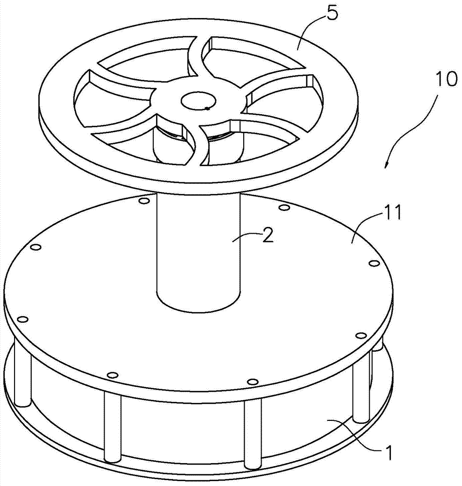
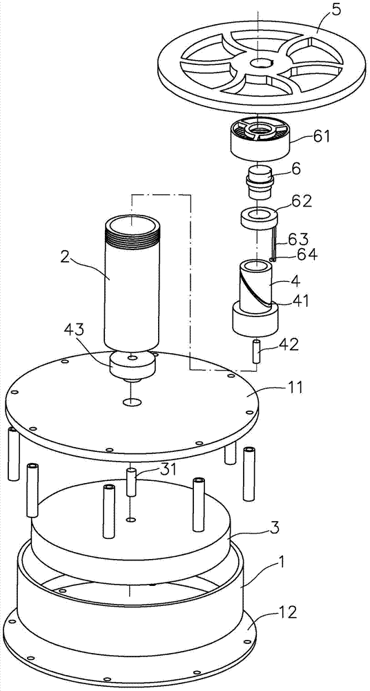
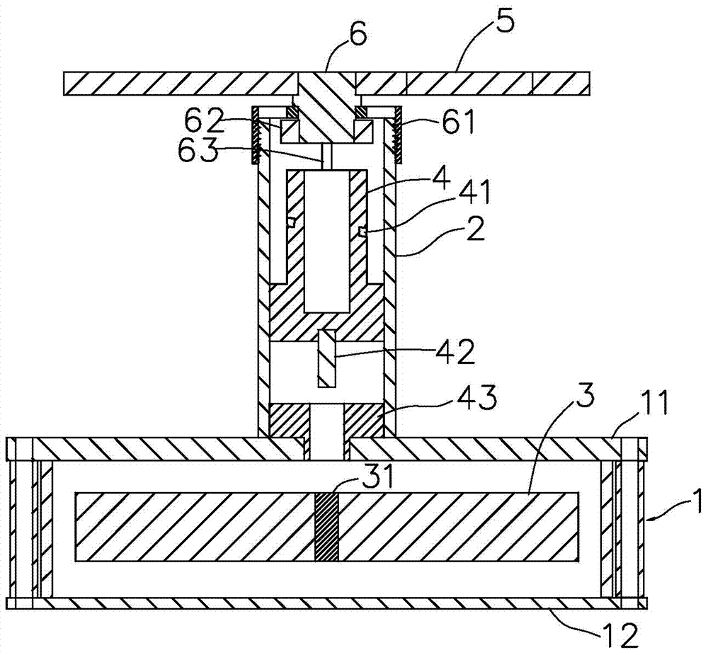
[0040] Example 1, such as figure 1 , figure 2 and image 3 As shown, the Stirling engine 10 in this embodiment includes a first cylinder 1, a second cylinder 2, a gas displacement piston 3 and a power piston 4, the lower end surface of the first cylinder 1 forms a heat absorbing surface 12, and the upper end surface forms a heat dissipation surface 11. The second cylinder 2 is in communication with the first cylinder 1; the moving piston 3 is set in the first cylinder 1 so that it can move up and down; the power piston 4 is set in the second cylinder 2 so that it can move up and down.

[0041] The bottom end of the power piston 4 is provided with a magnet 42 and a guide groove 41 is obliquely formed on the outer periphery. Of course, it is also possible to form the middle part of the power piston 4 as hollow and form the guide groove 41 on the inner wall. However, it is preferable to arrange it on the outer periphery.

[0042] The air-moving piston 3 is provided with a dri...

Embodiment 2

[0045] Example 2, such as Figure 4As shown, the cup in this embodiment includes a cup body 100 and a cup cover 102 covering the cup body 100. The cup cover 102 includes a body 7 and a heat insulating sleeve 8 disposed in the body 7. The middle part of the cup cover 102 has a The mounting hole for the first cylinder 1 of the Stirling engine 10 to extend into, the heat absorbing surface 12 and the heat dissipation surface 11 of the Stirling engine 10 are adapted to the upper end surface and the lower end surface of the body 7 respectively, and the outer side of the cup cover 102 is detached A cover body 101 is provided in a conventional manner, and the Stirling engine 10 is located in the cover body 101 . For the structure of the Stirling engine 10, refer to Embodiment 1. During use, add hot water in the cup body 100, take off the cover body 101, put the cup cover 102 on the cup body 100, after a few minutes, drive the flywheel 5, and the flywheel 5 can continue to rotate.

Embodiment 3

[0046] Example 3, such as Figure 5 As shown, the cup in this embodiment includes a cup body 100 and a cup cover 102 covering the cup body 100. The cup cover 102 includes a body 7 and a heat insulating sleeve 8 disposed in the body 7. The Stirling engine 10 The cooling surface 11 and the body 7 are one piece, the inner wall of the heat insulation sleeve 8 forms the first cylinder side wall of the Stirling engine, and the heat absorption surface 12 of the Stirling engine 10 is embedded in the lower end surface of the heat insulation sleeve 8 . Refer to Example 2 for other structures.


PUM


Abstract

The invention provides a stirling engine. The stirling engine comprises a first cylinder, a second cylinder, an air moving piston and a power piston. The stirling engine is characterized in that the bottom end of the power piston is arranged to a magnet, and a guide groove is obliquely formed in the periphery or the inner wall of the power piston; a driving block which is in match with the magnet by magnetic attracting through a clearance manner is arranged on the air moving piston; a flywheel is arranged on the top end of the second cylinder through a rotating shaft; the rotating direction of the flywheel is perpendicular to the moving direction of the power piston; the rotating shaft is downwards connected with a driving rod; the end part of the driving rod is arranged in the guide groove and can move along the guide groove. The invention further discloses a cup cover and a cup which are both provided with the engine. Compared with the prior art, the stirling engine has the advantages that the power piston drives the flywheel through the driving rod to rotate in the horizontal direction, so that the structure and type of the existing stirling engine model is enriched; the whole structure is compact, and the design is nice.

Description

technical field [0001] The invention relates to a Stirling engine, and the invention also relates to a cup cover and a cup with the Stirling engine. Background technique [0002] Existing cups are of a great variety, in various shapes and with various functions, but basically consist of a cup cover and a cup body, which lack novelty. In addition, as we all know, the Stirling engine is an external combustion engine, which avoids the shock work and intermittent combustion process similar to the internal combustion engine, and has the advantages of high efficiency, low noise and low emission. The basic principles of the cycle process involved are as follows: Stages: ①compression process at constant temperature; ②endothermic process at constant volume; ⑧expansion process at constant temperature; ④exothermic process at constant volume, completing a cycle. Under ideal endothermic conditions, the thermal efficiency of this cycle is equal to the Carnot cycle with the same upper and...

Claims


Application Information

Patent Timeline
Patent Type & Authority Applications(China)
IPC IPC(8): F02G1/043A47G19/22A47G19/24
CPCA47G19/2205A47G19/24F02G1/043F02G1/044F02G1/053
Inventor 魏亮
Owner NINGBO XIAYUAN TECH
Why Eureka
Try Eureka