Eureka AIR delivers breakthrough ideas for toughest innovation challenges, trusted by R&D personnel around the world.

Hydraulic oil tank for mulch applicator

A technology of hydraulic oil tank and laminating machine, which is applied in the direction of oil supply tank device, mechanical equipment, fluid pressure actuating device, etc., can solve the problems of increasing cost, prolonging processing cycle, hidden danger of oil leakage in oil tank, etc., and achieving low production cost, The effect of improving strength and convenient processing

Inactive Publication Date: 2015-07-01
崔国锐
View PDF7 Cites 0 Cited by
  • Summary
  • Abstract
  • Description
  • Claims
  • Application Information

AI Technical Summary

Problems solved by technology

For different products to be processed, in order to achieve the same effect, different pressures are required, so the pressure roller needs to be controlled by a hydraulic rod, and the oil pipe of the hydraulic rod is connected to the hydraulic oil tank. Most of the existing oil tanks are made of thin plates. and heat dissipation effect, it is necessary to weld the rib structure on the outside of the fuel tank, which prolongs the processing cycle and increases the production cost. At the same time, the welding process will bring hidden dangers to the oil leakage of the fuel tank

Method used


Image

  • Hydraulic oil tank for mulch applicator

Examples


Embodiment Construction

[0012] The present invention is described in further detail now in conjunction with accompanying drawing. These drawings are all simplified schematic diagrams, which only illustrate the basic structure of the present invention in a schematic manner, so they only show the configurations related to the present invention.

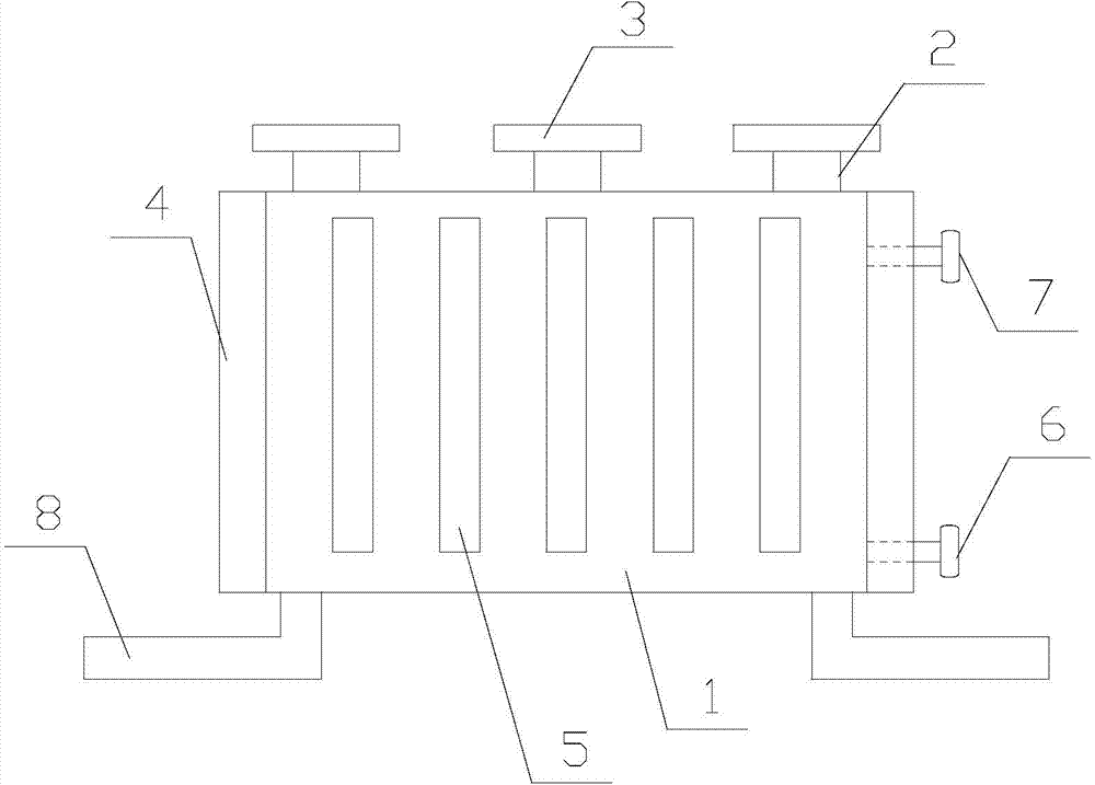
[0013] Such as figure 1 The hydraulic oil tank for the laminating machine shown has a box body 1 with a rectangular structure, and several connecting shells 2 are evenly distributed on the top surface of the box body 1, and a heat sink 3 is arranged on the connecting shell 2. The left side of the box body 1 and The right side is provided with a plurality of mutually parallel ribs 4, and several ribs 5 are evenly distributed on the front side and the rear side of the box body 1. The ribs 4 and the ribs 5 are integrally formed with the box body 1 to improve the The strength of the box body 1 is also conducive to heat dissipation. The lower end of the side wall ...


PUM


Abstract

The invention relates to a hydraulic oil tank for a mulch applicator. The hydraulic oil tank comprises a tank body of a rectangular structure, a plurality of connecting shells are evenly distributed on the top face of the tank body, cooling fins are arranged on the connecting shells, multiple parallel protruding edges are arranged on the left side and the right side of the tank body, a plurality of reinforcing ribs are evenly distributed on the front surface and the rear surface of the tank body, and the protruding ribs, the reinforcing ribs and the tank body are of an integrally formed structure; an oil inlet pipe opening is formed in the lower end of the side wall of the tank body, an oil outlet pipe opening is formed in the upper end of the side wall of the tank body, and flanges are arranged on the outer portion of the oil inlet pipe opening and the outer portion of the oil outlet pipe opening; the number of the reinforcing ribs is ten, and fixing bottom feet are arranged at the bottom of the tank body. The hydraulic oil tank for the mulch applicator is simple in structure, the protruding edges and the reinforcing ribs on the side wall of the tank body are integrally formed, the strength of the tank body is improved, cooling of hydraulic oil in the tank body is facilitated, machining is convenient, production cost is low, and the cooling fins arranged on the top face of the tank body can also enhance the cooling effect, so that long-time use is facilitated.

Description

technical field [0001] The invention relates to a hydraulic oil tank for a laminating machine. Background technique [0002] During the laminating process, the laminating machine directly sticks the sticky film to the surface of the product to be processed through the pressure of the pressure roller. This step of pressure can make the film closely adhere to the product to be processed, making the surface bright , Bright color and waterproof function. For different products to be processed, in order to achieve the same effect, different pressures are required, so the pressure roller needs to be controlled by a hydraulic rod, and the oil pipe of the hydraulic rod is connected to the hydraulic oil tank. Most of the existing oil tanks are made of thin plates. In order to improve the heat dissipation effect, it is necessary to weld the rib structure on the outside of the fuel tank, which prolongs the processing cycle and increases the production cost. At the same time, the weldi...

Claims


Application Information

Patent Timeline
Patent Type & Authority Applications(China)
IPC IPC(8): F15B1/26F15B21/04
CPCF15B1/26F15B21/042
Inventor 崔国锐
Owner 崔国锐
Why Eureka
Eureka Blog
Learn More