Engineering machinery movable arm potential energy variable amplitude energy recovery device

An energy recovery device, boom potential energy technology, applied in fluid pressure actuation devices, mechanical equipment, earth movers/shovels, etc., can solve the problem of low energy recovery efficiency, low power generation and battery or capacitor charging efficiency, energy The problem of not being able to release and other problems can achieve the effect of realizing energy recovery and utilization, rapid energy recovery and utilization, and fewer energy conversion times.

Active Publication Date: 2015-07-01
TONGJI UNIV
View PDF13 Cites 14 Cited by
  • Summary
  • Abstract
  • Description
  • Claims
  • Application Information

AI Technical Summary

Problems solved by technology

The first is the high cost of electrical energy storage units such as high-performance batteries and supercapacitors, which limits the practical application of this solution
The second is that the lowering process of the boom takes a very short time, and in the process of large changes in the rotational speed, the power generation of the generator and the charging efficiency of the battery or capacitor are low
The third is that the repeated conversion of mechanical energy, pressure energy, and electrical energy greatly reduces the utilization rate of energy recovery
However, the previous hydraulic ener

Method used


Image

  • Engineering machinery movable arm potential energy variable amplitude energy recovery device
  • Engineering machinery movable arm potential energy variable amplitude energy recovery device

Examples


Embodiment 1

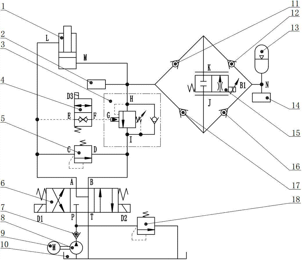
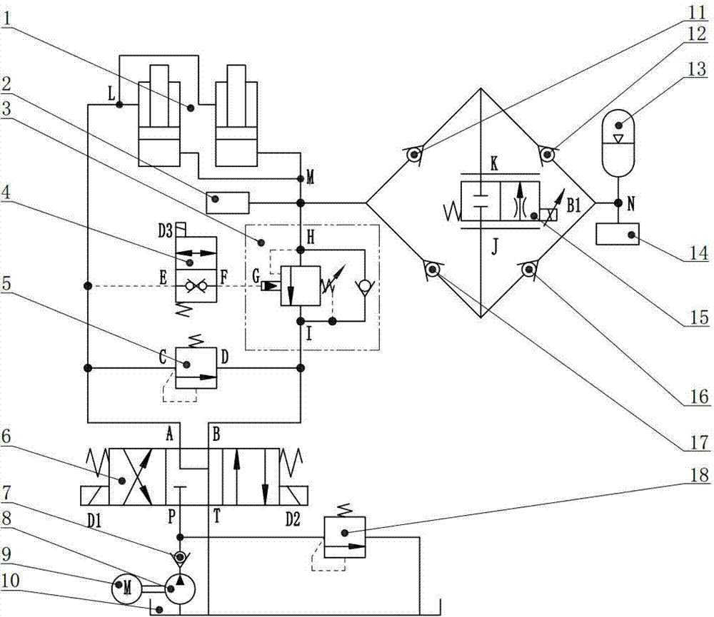
[0031] A kind of typical model of engineering machinery is excavator, and the technical scheme provided according to the present invention has designed figure 2 The shown excavator arm potential energy amplitude-changing energy recovery system is an example of the present invention, but this is not the only example implementing the technical solution of the present invention.

[0032] figure 2 The shown excavator boom potential energy luffing energy recovery system includes two boom cylinders, two pressure sensors, balance valves, two-position two-way solenoid valves, two overflow valves, three-position four-way electromagnetic reversing valves, five check valves, hydraulic pumps, electric motors, fuel tanks, accumulators, proportional flow valves and controllers.

[0033] Such as figure 2 As shown, two boom cylinders 1, first pressure sensor 2 and second pressure sensor 14, balance valve 3, two-position two-way solenoid valve 4, first relief valve 5 and second relief val...


PUM


Abstract

The invention relates to an engineering machinery movable arm potential energy variable amplitude energy recovery device which comprises a movable arm oil cylinder, a pressure sensor, a balance valve, a two-position two-way electromagnetic valve, overflow valves, a three-position four-way electromagnetic reversing valve, one-way valves, a hydraulic pump, a motor, an oil tank, an energy accumulator, a proportional flow valve and a controller. The motor is in mechanical transmission connection with the hydraulic pump. The hydraulic pump is connected with the oil tank and the one-way valves. The three-position four-way electromagnetic reversing valve is connected with the one-way valves, the oil tank, the movable arm oil cylinder and the balance valve. The balance valve is connected with a large-cavity oil port of the movable arm oil cylinder and the two-position two-way electromagnetic valve. The two-position two-way electromagnetic valve is connected with the three-position four-way electromagnetic reversing valve. The first overflow valve is connected with the three-position four-way electromagnetic reversing valve. The proportional flow valve is connected with the one-way valves. A proportional flow valve oil port is connected with the one-way valve. The third one-way valve is connected with the fourth one-way valve and the energy accumulator. The second overflow valve is connected with the one-way valves and the oil tank. The energy recovery device has the advantages of saving energy, recovering variable amplitude energy and being fast in dynamic response.

Description

technical field [0001] The invention relates to a potential energy recovery and regeneration device of a construction machinery boom, in particular to a construction machinery boom potential energy amplitude-changing energy recovery device using an accumulator, which belongs to the technical field of construction machinery. Background technique [0002] Construction machinery is a kind of engineering and construction machinery products that are widely used. With the continuous increase in the number of construction machinery, the energy consumed by a large number of construction machinery and the pollutants discharged have a serious impact on the environment. Energy-saving and efficient new construction machinery products have become the research and development goals of construction machinery at home and abroad. [0003] During the operation of construction machinery, the mass and inertia of the on-load working device are large, and most of the gravitational potential ener...

Claims


Application Information

Patent Timeline
IPC IPC(8): F15B21/14E02F9/22
CPCE02F9/2217F15B21/14
Inventor 卞永明易万力刘广军李安虎
Owner TONGJI UNIV
Why Eureka
Try Eureka