Optical machine structure based on infrared area array detector scanning and imaging

A detector, opto-mechanical technology used in the field of infrared detection systems to solve problems such as blurring and smearing

Inactive Publication Date: 2015-07-01
SHANGHAI INST OF TECHNICAL PHYSICS - CHINESE ACAD OF SCI
View PDF6 Cites 3 Cited by
  • Summary
  • Abstract
  • Description
  • Claims
  • Application Information

AI Technical Summary

Problems solved by technology

The continuous rotation imaging of the area array detector will inevitably produce blurring and smearing of the image, which is a major defect of the continuous scanning technology of the area array detector

Method used


Image

  • Optical machine structure based on infrared area array detector scanning and imaging
  • Optical machine structure based on infrared area array detector scanning and imaging
  • Optical machine structure based on infrared area array detector scanning and imaging

Examples


Embodiment Construction

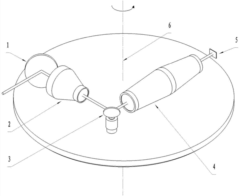
[0014] According to attached figure 1 The diagram of the marked:

[0015] The pitch pointing mirror 1 is a plane mirror with adjustable pitch angle, and its function is to adjust the pitch angle value of the imaging field of view. The value of the pitch angle is generally adjusted before the system works, and the pitch pointing mirror 1 remains fixed after the integration of the detector starts.

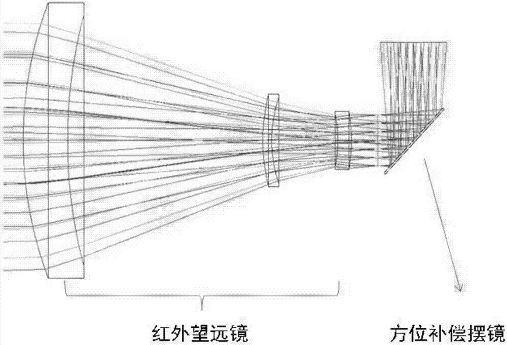
[0016] The infrared telescopic lens 2 is an infrared optical system with no optical power, and its function is to compress the infinite parallel light beam at the entrance pupil to the exit pupil, and exit as parallel light. Its angular magnification is γ. It can be obtained from the characteristics of the telescopic optical system that the ratio of the entrance pupil size to the exit pupil size is also γ. The larger the γ, the smaller the size of the azimuth compensation oscillating mirror 3 in the subsequent optical path, which is beneficial for the motor to control the oscilla...


PUM


Abstract

The invention discloses an optical machine structure based on infrared area array detector scanning and imaging. The structure comprises a pitching orientating lens 1, an infrared telescope lens 2, a direction compensation pendulum lens 3, an infrared imaging lens 4, an infrared area array focal plane detector 5 and a direction scanning rotary table 6. By the aid of the structure, one single infrared area array detector is capable of scanning and imaging overall by 360 degrees, the fuzzy effect is prevented during infrared image acquisition due to rotation of the platform, and the advantages of long integral time and high sensitivity of the infrared area array focal plane detector can be played fully. The structure has the advantages that overall scanning is implemented, image fuzzy slur is avoided, and the telescope structure and a secondary imaging objective lens structure are combined.

Description

Technical field: [0001] The invention relates to an infrared detection system, in particular to a scanning detection system based on an area array detector. Background technique: [0002] The second-generation infrared warning system has been studied abroad since the late 1970s, and it has been more than 30 years. The second-generation infrared warning system uses infrared array detectors to scan and image at a speed of about 1 Hz. Due to the constraints of the line scan imaging mechanism, the performance of the second generation infrared warning system is limited by short integration time and low frame rate. [0003] The third-generation infrared warning system generally uses area array infrared detectors for staring imaging, and its integration time is increased from tens of microseconds in the second generation to milliseconds, and the staring frame rate can be as high as 100Hz. Therefore, the warning accuracy and distance indicators of the third-generation infrared war...

Claims


Application Information

Patent Timeline
Patent Type & Authority Applications(China)
IPC IPC(8): G01J5/08H04N5/225H04N5/33
Inventor 蹇毅朱承希高思莉
Owner SHANGHAI INST OF TECHNICAL PHYSICS - CHINESE ACAD OF SCI
Why Eureka
Try Eureka