Sparse stepped-frequency SAR imaging method under spatial-frequency-domain two-dimensional condition

A technology of stepping frequency and imaging method, which is applied in the field of remote sensing detection and radar imaging, and can solve problems such as ineffective response, incomplete data acquisition, and missing airspace.

Active Publication Date: 2015-07-01
INST OF ELECTRONICS CHINESE ACAD OF SCI
View PDF1 Cites 9 Cited by
  • Summary
  • Abstract
  • Description
  • Claims
  • Application Information

AI Technical Summary

Problems solved by technology

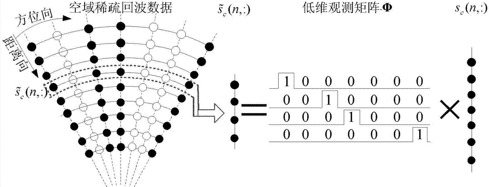
[0005] At the same time, within the azimuth accumulation time of SAR imaging, due to changes in the working state of the radar carrier aircraft, changes in flight attitude or the needs of practical applications, the azimuth data acquisition will be incomplete or missing, that is, the airspace is sparse. The traditional method will not be able to effectively deal with the azimuth imaging processing

Method used


Image

  • Sparse stepped-frequency SAR imaging method under spatial-frequency-domain two-dimensional condition
  • Sparse stepped-frequency SAR imaging method under spatial-frequency-domain two-dimensional condition
  • Sparse stepped-frequency SAR imaging method under spatial-frequency-domain two-dimensional condition

Examples


example 1

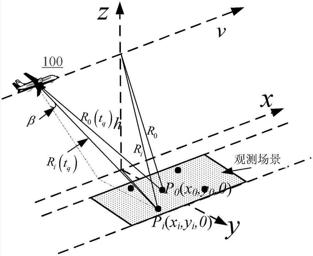
[0068] Example 1 is verified by simulation experiment. The relevant initial parameters in the simulation experiment are as follows: The observation scene consists of 285 scattering points, such as Figure 4A Shown. The carrier frequency of the radar signal f 0 Is 10GHz, the frequency step value of the step frequency signal is Δf=1.5MHz, each pulse includes 600 sub-pulses, the obtained composite bandwidth B=900MHz, and the obtained range resolution Δ R =0.17m. The closest distance between the center of the observation scene and the flight path of the carrier is 10km, the flying speed of the carrier is 100m / s, the imaging time is 1.5s, the radar aperture is 1m, and the azimuth resolution Δ obtained C =0.5m.

[0069] The high-resolution range image of the scene and the two-dimensional SAR imaging results obtained by using the uniform step frequency signal in the prior art are as follows Figure 4B with Figure 4C Shown. For each pulse train of the step frequency signal, half of the...

example 2

[0071] Example 2 A ground-based experiment was performed, and the actual measurement data was used to verify the effect of the present invention. Figure 5A Indicates the layout of the experimental scene. The relevant initial parameters in the experiment are as follows: The experimental system adopts the working mode of transmitting and receiving at the same time, the step frequency signal is transmitted from the output port of the vector network analyzer through the ka-band horn antenna, and the echo signal is sent to the vector network analyzer from the antenna Enter the port. The length of the antenna track is 1.89m, and the antenna interval is 0.01m. A total of 189 echo signals are collected during full sampling. The transmitted signal is a stepped frequency signal with a carrier frequency of 30GHz, a bandwidth of 6GHz, a frequency interval of Δf of 1.25MHz, and a total of 1600 sub-pulses, such as Figure 5B As shown, five metal balls with a diameter of 0.05m were set as o...


PUM


Abstract

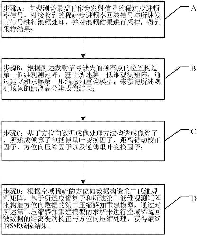
The invention provides a sparse stepped-frequency signal SAR imaging method under the spatial-frequency-domain two-dimensional condition. The sparse stepped-frequency signal SAR imaging method is technically characterized in that a sparse stepped-frequency signal echo model is analyzed, a compressed sensing theory is combined and sparse stepped-frequency points are utilized to obtain a high-resolution distance imaging result; under the situation of SAR space domain data missing, range migration correction and orientation compression processing of echo data are achieved by establishing an imaging operator and a compression sensing reconstruction model, and further a final SAR imaging result is obtained. Compared with traditional even sparse stepped-frequency signal SAR imaging, the method can achieve SAR imaging only by needing few frequency resources and small radar echo numbers, interfered frequency points can be jumped over and the anti-interference capacity can be improved by utilizing the sparse stepped-frequency signals, meanwhile signal transmitting duration is shortened, equivalent repeating frequency is improved, and azimuth Doppler fuzzy is avoided.

Description

Technical field [0001] The invention relates to the technical field of remote sensing detection and radar imaging, in particular to a SAR imaging method of stepped frequency signals. Background technique [0002] Synthetic Aperture Radar (SAR) can achieve all-weather, all-weather, high-gain ground scene imaging, specifically to achieve high range resolution through a wide signal band design; through the movement of the radar carrier platform, equivalently The space forms a long linear array to achieve high resolution in azimuth. However, due to the limitation of the hardware level, the increase in signal bandwidth is far behind people's requirements for imaging resolution, so people have proposed stepped frequency signals. Using this stepped frequency signal, a high-resolution range image can be synthesized through digital signal processing without increasing the instantaneous bandwidth of the radar system. [0003] However, the frequency step value of the traditional step freque...

Claims


Application Information

Patent Timeline
Patent Type & Authority Applications(China)
IPC IPC(8): G01S13/90
CPCG01S13/9011G01S13/9004
Inventor 洪文张群顾福飞罗迎蒋成龙张冰尘
Owner INST OF ELECTRONICS CHINESE ACAD OF SCI
Why Eureka
Try Eureka