Heat dissipating rack for solid-sealed polar pole

A technology of solid-sealed poles and heat sinks, which is applied in the field of heat sinks, can solve the problems of affecting the service life of vacuum interrupters and circuit breakers, the small area of ​​arc spot melting zone, and the rise of contact temperature, and achieves simple structure and metal vapor The effect of low concentration and good thermal conductivity

Inactive Publication Date: 2015-07-01
施周平
View PDF3 Cites 2 Cited by
  • Summary
  • Abstract
  • Description
  • Claims
  • Application Information

AI Technical Summary

Problems solved by technology

Therefore, the arc spot melting zone on the contact surface has a small area, shallow depth, and small thermal inertia. The current is often as high as 2000A. The passage of a large cu

Method used


Image

  • Heat dissipating rack for solid-sealed polar pole
  • Heat dissipating rack for solid-sealed polar pole
  • Heat dissipating rack for solid-sealed polar pole

Examples


Embodiment Construction

[0014] The present invention will now be further described in conjunction with specific examples, and the following examples are intended to illustrate the present invention rather than further limit the present invention.

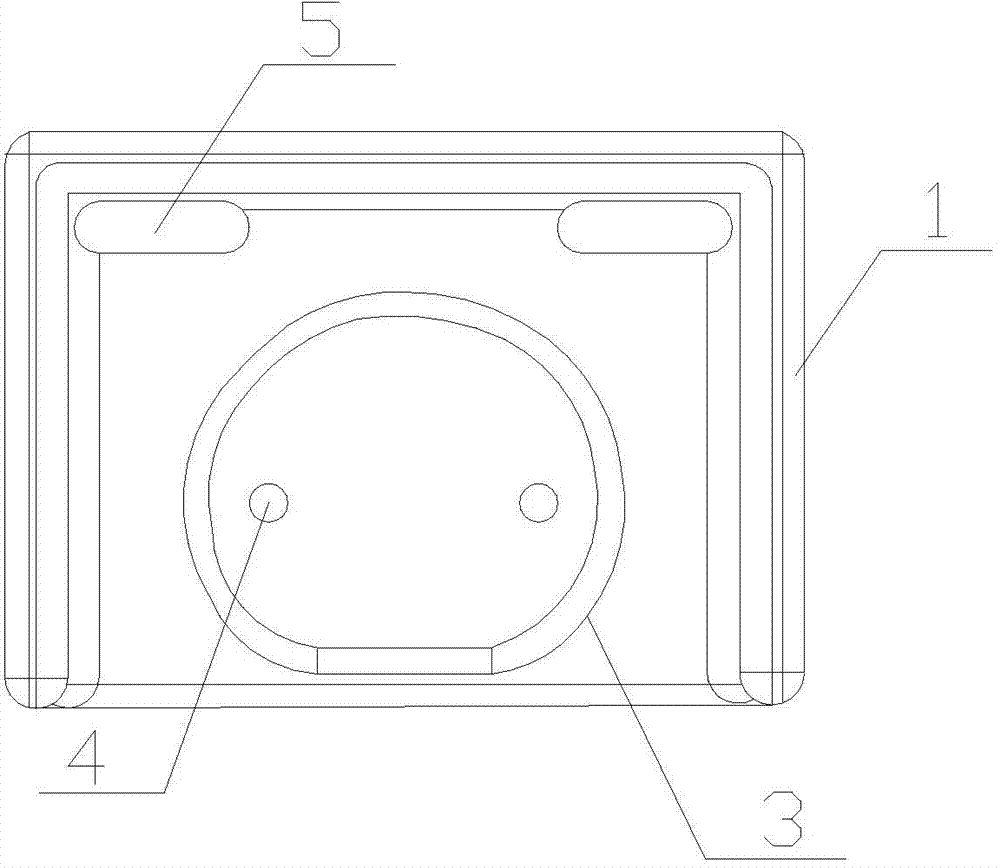
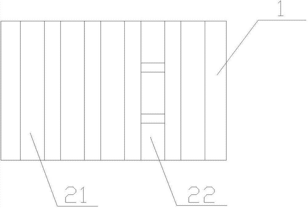
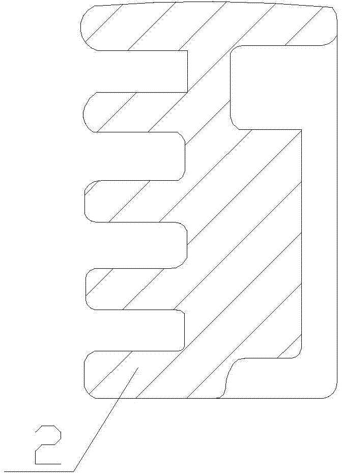
[0015] Such as Figure 1~3 As shown, a heat sink for solid sealing on poles includes a heat sink body. The heat sink body includes a door-shaped bottom plate 1 and a heat sink 2 located on the bottom plate 1. The heat sink 2 includes a strip-shaped structure. Radiating fins 21 and radiating fins 22 with a wave-shaped structure, the back of the base plate 1 is provided with a connecting seat 3 connected to the solid-sealed pole, the connecting seat 3 is provided with threaded holes 4, and the four corners of the base plate 1 are also provided with Seal 5.

[0016] Further, there are five cooling fins 2, one of which is a cooling fin 22 with a wave-shaped structure. The heat sinks 2 of the prior art are all strip-shaped heat sinks 21, and one of the heat s...


PUM


Abstract

The invention relates to switch equipment parts in power systems, particularly to a heat dissipating rack for a solid-sealed polar pole. The heat dissipating rack for the solid-sealed polar pole comprises a heat dissipating rack body. The heat dissipating rack body comprises a bottom plate in a door-shaped structure and heat dissipating fins arranged on the bottom plate, wherein the heat dissipating fins are composed of bar-shape-structured heat dissipating fins and wave-shape-structured heat dissipating fins; the back surface of the bottom plate is provided with a connecting seat connected with the solid-sealed polar pole; the connecting seat is provided with a threaded hole; the four corners of the bottom plate are provided with sealing members. The heat dissipating rack for the solid-sealed polar pole is simple in structure and reasonable in design, obtains good thermal conductivity and can cool cathode spots and reduce metal vapor concentration, thereby ensuring normal on and off of a vacuum arc-extinguishing chamber.

Description

technical field [0001] The invention relates to spare parts of switchgear in a power system, in particular to a cooling frame used for solid sealing poles. Background technique [0002] Vacuum interrupter, also called vacuum switch tube or vacuum bubble, is the core device of vacuum circuit breaker (switch), and is installed in a solid-sealed pole. It uses a pair of electrodes (contacts) and other parts sealed in a vacuum to realize the closing or breaking of the circuit with the help of the excellent insulation and arc extinguishing performance of the vacuum. After cutting off the power supply, it can quickly extinguish the arc and suppress the current vacuum. device. [0003] In the process of breaking the current in the vacuum interrupter, the welding of the contacts in the vacuum switch is a prominent problem. The welding between the vacuum contacts is almost inevitable, so the welding force between the contacts can only be required to be not too large. After the weldi...

Claims


Application Information

Patent Timeline
IPC IPC(8): H01H33/66H01H9/52
CPCH01H33/66H01H9/52H01H2009/526H01H2033/6613
Inventor 施周平
Owner 施周平
Why Eureka
Try Eureka