Photoelectric oscillator

A photoelectric oscillator and oscillator technology, applied in the field of communication, can solve the problems of noise enhancement, reducing the stability of electrical clock and optical clock, etc., and achieve the effect of stabilizing electrical signals and eliminating common mode components

Inactive Publication Date: 2015-07-01
BEIJING UNIV OF POSTS & TELECOMM
View PDF4 Cites 14 Cited by
  • Summary
  • Abstract
  • Description
  • Claims
  • Application Information

AI Technical Summary

Problems solved by technology

[0004] The technical problem to be solved by the present invention is that the traditional double-loop OEO uses an electric coupler to add the microwave signals of the double loop, so that the noise is strengthened by superposition, and the stability of the generated electrical clock and optical clock is reduced.

Method used


Image

  • Photoelectric oscillator
  • Photoelectric oscillator
  • Photoelectric oscillator

Examples


Embodiment Construction

[0035] In order to make the purpose, technical solutions and advantages of the embodiments of the present invention clearer, the technical solutions in the embodiments of the present invention will be clearly described below in conjunction with the accompanying drawings in the embodiments of the present invention. Obviously, the described embodiments are the Some, but not all, embodiments are invented. Based on the embodiments of the present invention, all other embodiments obtained by persons of ordinary skill in the art without making creative efforts belong to the protection scope of the present invention.

[0036] A photoelectric oscillator comprising:

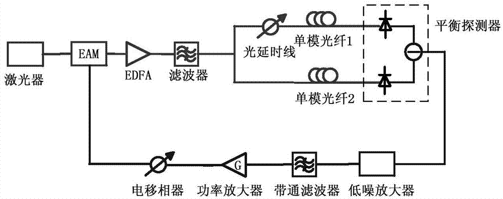
[0037] The balance detector is used to convert the two input optical pulse sequences into microwave signals, subtract the obtained two microwave signals, and output the subtracted microwave signals.

[0038] Preferably, the oscillator further includes: a first optical fiber, a second optical fiber, and a low-noise amplifi...


PUM


Abstract

The invention discloses a photoelectric oscillator, comprising a balance detector for converting two paths of input optical pulse sequences into microwave signals, subtracting two paths of obtained microwave signals and then outputting the subtracted microwave signals.

Description

technical field [0001] The invention relates to the communication field, in particular to a photoelectric oscillator. Background technique [0002] Optoelectronic oscillators (Optoelectronic Oscillator, OEO) have great potential application value in the fields of light sensing, radar, wireless communication, etc., so it has attracted great attention. The traditional double-ring OEO structure such as figure 1 As shown, the continuous optical signal sent by the laser is input into the electro-optic modulator, and the modulated optical signal is transmitted in two optical fiber links with different lengths, and then converted into a microwave signal after passing through a photodetector, and the microwave signal is filtered by a band-pass filter Side mode and noise, the amplification of the power amplifier and the phase modulation of the electric phase shifter, the microwave electric signal is fed back to drive the electro-optical modulator, thus forming the entire loop. The ...

Claims


Application Information

Patent Timeline
Patent Type & Authority Applications(China)
IPC IPC(8): H01S1/00
Inventor 伍剑臧继召李岩虞淼
Owner BEIJING UNIV OF POSTS & TELECOMM
Why Eureka
Try Eureka