A delay locked loop

A delay locking ring and delay chain technology, applied in the direction of electrical components, automatic power control, etc., can solve the problems of narrow application range, inability to provide static phase difference application requirements, poor flexibility, etc., and achieve the effect of high locking accuracy

Active Publication Date: 2017-10-31
INST OF ELECTRONICS CHINESE ACAD OF SCI
View PDF1 Cites 0 Cited by
  • Summary
  • Abstract
  • Description
  • Claims
  • Application Information

AI Technical Summary

Problems solved by technology

[0008] However, the existing delay-locked loop provides fixed four-phase or more phase output with a fixed static phase difference, which cannot provide the application requirements of fewer output phases and better static phase difference, and the application range is narrow
In addition, the existing delay-locked loop cannot improve the locking accuracy correspondingly with the reduction of the number of output phases, and the flexibility is poor

Method used


Image

  • A delay locked loop
  • A delay locked loop
  • A delay locked loop

Examples


Embodiment Construction

[0031] In order to make the object, technical solution and advantages of the present invention clearer, the present invention will be described in further detail below in conjunction with specific embodiments and with reference to the accompanying drawings. It should be noted that, in the drawings or descriptions of the specification, similar or identical parts all use the same figure numbers. Implementations not shown or described in the accompanying drawings are forms known to those of ordinary skill in the art. Additionally, while illustrations of parameters including particular values ​​may be provided herein, it should be understood that the parameters need not be exactly equal to the corresponding values, but rather may approximate the corresponding values ​​within acceptable error margins or design constraints.

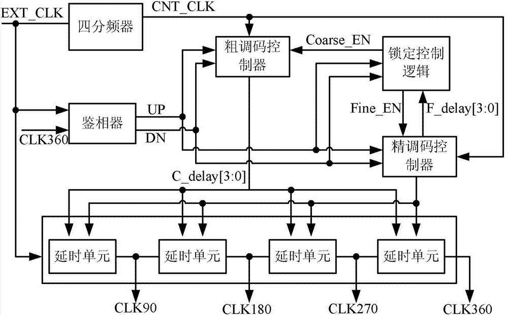
[0032] figure 2 It is a structural block diagram of a delay-locked loop in an embodiment of the present invention. Such as figure 2 As shown, the delay lo...


PUM


Abstract

The invention provides a delay locked loop, comprising: a digitally controlled delay chain, which adjusts the delay of the digitally controlled delay chain, and outputs a clock signal in a corresponding output mode; a phase detection logic circuit, according to the reference clock and Whether the delay difference of the feedback clock falls within the locking accuracy range Generate and output the lead or lag signal, lock logic signal; digitally control the delay chain control code generation circuit, and initially generate the rough delay chain control code according to the cycle size of the reference clock , then generate said other fine-tuning delay chain control codes according to the delay difference between the reference clock and the feedback clock, and finally adjust the fine-tuning delay chain control codes according to the lead or lag signal; the multi-mode selection control circuit, according to the working mode The selection signal control circuit is in a corresponding working mode, and at the same time combined with the locking logic signal to control the multi-mode selection control circuit to generate and output the first-bit fine-tuning delay chain control code in the corresponding working mode.

Description

technical field [0001] The invention relates to the technical field of integrated circuits in the electronics industry, in particular to a delay-locked loop. Background technique [0002] The clock signal of a system or circuit is often used as a reference quantity for synchronously performing timing and ensuring error-free high-speed operation. When the internal circuit uses the clock signal source of the external circuit, the internal circuit often produces clock signal skew due to the timing gap between the external clock signal and the internal clock signal. The delay locked loop can compensate the skew of the clock signal so that the phase of the internal clock signal is equal to the phase of the external clock signal. [0003] The basic idea of ​​a delay-locked loop is to delay the output clock so that it can be perfectly aligned with a reference clock or produce a definite phase-shifted output. At the same time, because DLL has the advantage of being less susceptibl...

Claims


Application Information

Patent Timeline
Patent Type & Authority Patents(China)
IPC IPC(8): H03L7/08
Inventor 张丹丹杨海钢朱文锐高丽江李威黄志洪
Owner INST OF ELECTRONICS CHINESE ACAD OF SCI
Why Eureka
Try Eureka