Fruit picking workbench

A workbench, fruit technology, applied in the direction of picking machines, agricultural machinery and implements, applications, etc., can solve the problems of low picking efficiency and high labor intensity, and achieve the effect of improving flexibility, convenient storage and handling, and convenient cutting.

Inactive Publication Date: 2015-07-08
GUANGXI UNIV
8 Cites 23 Cited by

AI-Extracted Technical Summary

Problems solved by technology

[0004] The purpose of the present invention is to provide a fruit picking workbench, thereby overcoming the shortcomings of ...

Method used

Cutter 5 is erected on platform 4, and as shown in Figure 5, cutter comprises cutter 51 and operating handle 52, and operating handle 52 is arranged on platform 4 in a rotatable manner. Preferably, the operating handle 52 is slidably arranged on a slide rail 53, and the slide rail 53 is erected on the platform 4 in a rotatable manner, and the operating handle 52 can drive the tool 51 to slide along the slide rail 53 to extend The distance of the cutter 51 is lengthened or shortened, and the operating handle 52 can rotate along with the slide rail 53 , so that the direction and cutting angle of the cutter 51 can be adjusted. Therefore, the cutting knife 5 of the present invention has good flexibility and can cut the fruit stalk conveniently.
[0029] As shown in Figure 1, the cart 1 can be manually promoted or driven by a power source. The upper end of the cart 1 is provided with a base 11. Preferably, the cart 1 is provided with a fruit storage bin 12 for conveniently storing and transporting the fruit when picking the fruit.
[0032] The platform 4 is arranged on the forward and backward moving seat 3 by a lifting mechanism 8. As shown in FIG. 4 , the lifting mechanism 8 includes a scissor lifting frame 81 , a third rail 82 , a sliding frame 83 and a third driving mechanism. The upper end of the scissor lifting frame 81 is arranged at the bottom of the platform 4 . The legs on the right side of the scissor lift ...

Abstract

The invention discloses a fruit picking workbench. The fruit picking workbench comprises a trolley, a lateral movement base, a front and back movement base, a platform and a cutter; the upper end of the trolley is provided with a base; the lateral movement base is arranged on the base through a lateral movement mechanism; the front and back movement base is arranged on the lateral movement base through a front and back movement mechanism; the platform is arranged on the front and back movement base through a lifting mechanism; the cutter comprises a cutting tool and an operation handle which is connected with the cutting tool; the operation handle is arranged on the platform in a rotatable mode. According to the fruit picking workbench, workers can be conveyed to be near fruits through the platform to cut off fruit stems through the cutter, the use is safe and reliable, and the efficiency that the workers pick the fruits with the thick and hard fruit stems and the heavy and large fruit can be improved.

Application Domain

Technology Topic

Image

  • Fruit picking workbench
  • Fruit picking workbench
  • Fruit picking workbench

Examples

  • Experimental program(1)

Example Embodiment

[0026] The specific embodiments of the present invention will be described in detail below in conjunction with the drawings, but it should be understood that the protection scope of the present invention is not limited by the specific embodiments.
[0027] Unless otherwise expressly stated otherwise, throughout the specification and claims, the term "comprising" or its transformations such as "comprising" or "including" will be understood to include the stated elements or components, and not Other elements or other components are not excluded.
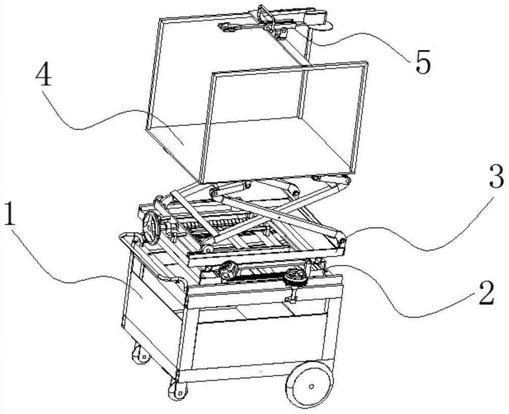
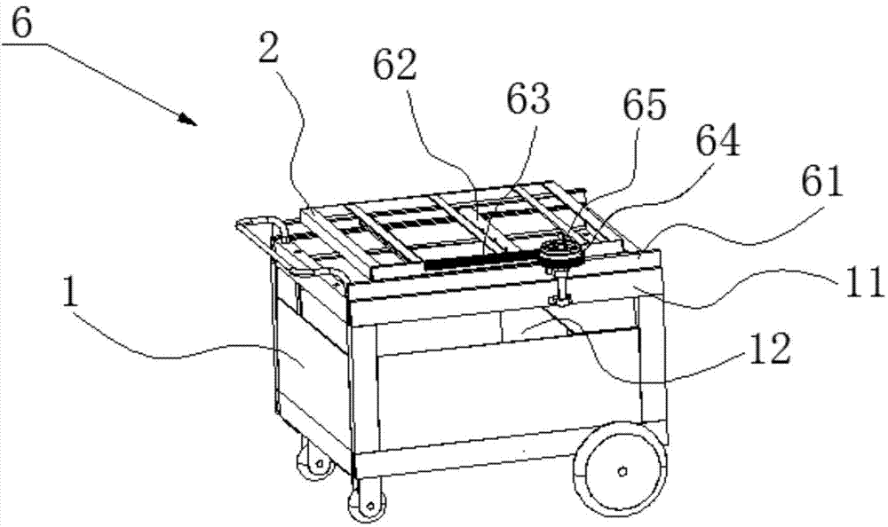
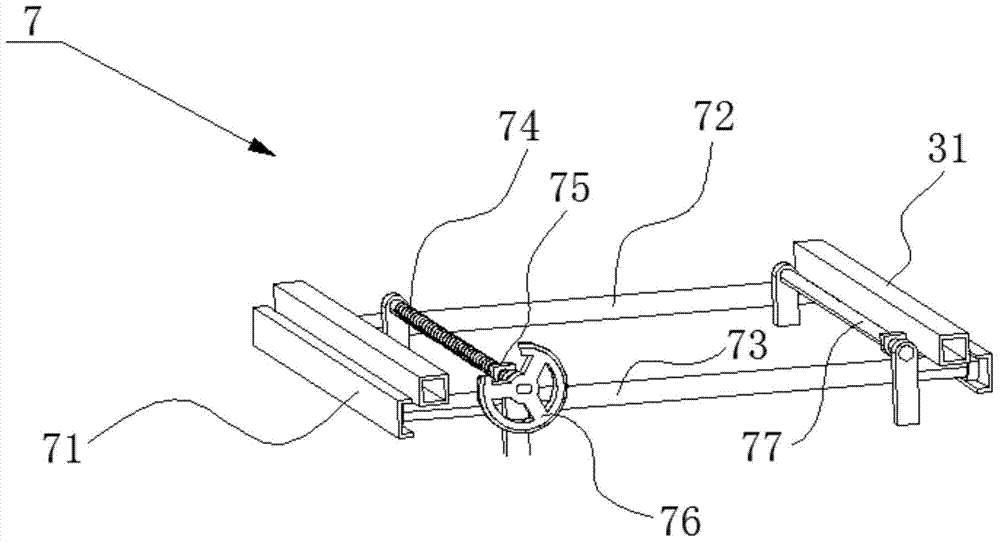
[0028] Such as Figure 1 to Figure 5 As shown, an example according to the specific implementation of the present invention is: a fruit picking workbench, which includes a cart 1, a left-right moving seat 2, a forward and backward moving seat 3, a platform 4, and a cutting knife 5, wherein:
[0029] Such as figure 1 As shown, the cart 1 can be manually pushed or driven by a power source. The cart 1 is provided with a base 11 at the upper end. Preferably, the cart 1 is provided with a fruit storage 12 to facilitate storage and transportation of fruits when picking fruits.
[0030] The left-right moving seat 11 is arranged on the base 11 through a left-right moving mechanism 6. Such as figure 2 As shown, the left-right moving mechanism 6 includes a first rail 61, a first moving shaft 62, and a first driving mechanism. The two first rails 61 are respectively disposed on the front and rear sides of the base 11. The front and rear ends of the two first moving shafts 62 are respectively slidably arranged on the two first rails 61, and the left and right moving seats 2 are arranged on the two first moving shafts 62 to be able to follow the two first moving shafts. The moving shaft 62 moves left and right. The first driving mechanism is used to drive the two first moving shafts 62 to slide left and right along the two first rails 61. Preferably, as figure 2 As shown, the first driving mechanism includes: a rack 63, a gear 64, and a first power source. The rack 63 is fixedly arranged on the left and right moving base 2; the gear 64 is rotatably arranged on the base 11, and the gear 64 and the gear The strip 63 is in meshing connection. The first power source is used to drive the gear 64 to rotate. Preferably, the first power source is a first hand wheel 65 arranged coaxially with the gear 64, and the worker drives the gear 64 to rotate by rotating the first hand wheel 65. In addition, the left-right moving seat 2 may be driven by a hydraulic device to move left and right.
[0031] The forward and backward moving seat 3 is arranged on the left and right moving seat 2 through a forward and backward moving mechanism 7. Such as image 3 As shown, the forward and backward moving mechanism 7 includes a second track 71, a support shaft 72, a second moving shaft 73, a forward and backward moving screw 74, and a second driving mechanism. The two second tracks 71 are respectively disposed on the left and right sides of the left and right moving seat 2. On the other hand, the support shaft 72 is rotatably installed on the front ends of the two second rails 71. The front part of the forward and backward moving seat 3 is movably supported on the supporting shaft 72. The second moving shaft 73 is provided at the rear of the two second rails 71 in a manner capable of sliding back and forth. The rear part of the forward and backward moving seat 3 is fixedly supported on the second moving shaft 73. Preferably, the bottom of the forward and backward moving seat 3 is provided with two cross beams 31, and the forward and backward moving seat 3 is connected with the supporting shaft 72 and the second moving shaft 73 through the two cross beams 31. The second driving mechanism is used to drive the second moving shaft 73 to slide back and forth along the two second rails 71. Preferably, the second driving mechanism includes a forward and backward moving screw 74, a connecting seat 45, and a second power source. The forward and backward moving screw 74 is rotatably mounted on the left and right moving seat 2, and the upper end of the connecting seat 75 is fixedly arranged at the front and rear. The bottom of the moving base 3 and the lower end of the connecting base 75 are engaged with the front and rear moving screw 74. The second power source is used to drive the forward and backward moving screw 74 to rotate, so as to drive the forward and backward moving base 3 and the second moving shaft 73 to move forward and backward along the second rail 71 through the connecting base 75. Such as image 3 As shown, the left and right moving seat 2 is also provided with a forward and backward moving guide rod 77 parallel to the forward and backward moving screw 74. The forward and backward moving guide rod 77 is connected to the bottom of the forward and backward moving seat through another connecting seat 77, and the forward and backward moving guide rod 77 It is possible to reduce the load of moving the screw 74 forward and backward, and enable the forward and backward moving seat 3 to move more smoothly. Preferably, the second power source is a second hand wheel 76 fixedly connected to one end of the forward and backward moving screw 74. The worker rotates the hand wheel 76 to drive the forward and backward moving screw 74 to rotate. In addition, the forward and backward movement seat 3 may be driven by a hydraulic device to move forward and backward.
[0032] The platform 4 is arranged on the forward and backward moving seat 3 through a lifting mechanism 8. Such as Figure 4 As shown, the lifting mechanism 8 includes a scissor lifting frame 81, a third rail 82, a sliding frame 83, and a third driving mechanism. The upper end of the scissor lifting frame 81 is arranged at the bottom of the platform 4. The right leg of the scissor lift 81 is hinged to the right end of the forward and backward moving base 3. The two third rails 82 are respectively arranged on the front and rear sides of the left end of the front and rear movable seat 3. The front and rear ends of the sliding frame 83 are respectively arranged on the two third rails 82 in a slidable manner, and the left leg of the scissor lift 81 is hinged to the sliding frame 83. The third driving mechanism is used to drive the sliding frame 83 to slide along the two third rails 81. Preferably, the third driving mechanism includes a lifting screw 84 and a third power source. The lifting screw 84 is rotatably arranged on the front and rear sliding seat 3, and the sliding frame 83 is provided with an engaging connection with the lifting screw 84. Screw holes. The third power source is used to drive the lifting screw 84 to rotate. Preferably, the third power source is a third hand wheel 85 fixedly arranged at one end of the lifting screw 84. Such as Figure 4 As shown, a lifting guide rod 86 parallel to the lifting screw 84 is erected on the front and rear moving seat, and the lifting guide rod 86 movably passes through the sliding frame 83. By providing the lifting guide rod 86, the load of the lifting screw 84 can be reduced, and the scissor-type lifting frame 81 can be driven for lifting more smoothly. In addition, the scissor lift 81 can also be lifted and lowered by a hydraulic device.
[0033] The cutter 5 is set up on the platform 4, such as Figure 5 As shown, the cutter includes a cutter 51 and an operating handle 52, and the operating handle 52 is arranged on the platform 4 in a rotatable manner. Preferably, the operating handle 52 is slidably arranged on a slide rail 53, the slide rail 53 is rotatably installed on the platform 4, and the operating handle 52 can drive the tool 51 to slide along the slide rail 53 to extend The distance of the cutter 51 is lengthened or shortened, and the operating handle 52 can rotate with the slide rail 53, so that the direction and cutting angle of the cutter 51 can be adjusted. Therefore, the cutting knife 5 of the present invention has good flexibility and can conveniently cut the fruit stem.
[0034] When picking fruits with thick, hard stalks and heavy fruits, the workbench is moved to a suitable position through the cart 1, and then the worker stands on the platform 4 and moves the position of the moving seat 2 and forward and backward by moving the position of the moving seat 2. The platform 4 is raised so that the platform 4 is aligned with the fruit. The worker then operates the cutter 5 to cut the stalk of the fruit, and the picked fruit can fall onto the platform 4 under the support of the worker. After the fruit is picked, the fruit can also be stored in the fruit storage bin of the cart 1. The structure of the invention is simple, and the workers are safe and reliable when picking fruits with thick, hard stalks and heavier fruits, the labor intensity of the workers is low, and the picking efficiency is high.
[0035] The foregoing description of specific exemplary embodiments of the present invention is for the purpose of illustration and illustration. These descriptions are not intended to limit the invention to the precise form disclosed, and it is obvious that many changes and changes can be made based on the above teachings. The purpose of selecting and describing the exemplary embodiments is to explain the specific principles of the present invention and its practical application, so that those skilled in the art can realize and use various exemplary embodiments of the present invention and various different Choice and change. The scope of the present invention is intended to be defined by the claims and their equivalents.

PUM

no PUM

Description & Claims & Application Information

We can also present the details of the Description, Claims and Application information to help users get a comprehensive understanding of the technical details of the patent, such as background art, summary of invention, brief description of drawings, description of embodiments, and other original content. On the other hand, users can also determine the specific scope of protection of the technology through the list of claims; as well as understand the changes in the life cycle of the technology with the presentation of the patent timeline. Login to view more.

Similar technology patents

Classification and recommendation of technical efficacy words

  • Simple structure
  • Easy to manufacture

Microlithographic projection exposure apparatus

InactiveUS20050068499A1Simple structureReliable and low-maintenance operationProjectorsPhotomechanical exposure apparatusCamera lensPhysics
Owner:CARL ZEISS SMT GMBH
Why Eureka
Try Eureka