Supercharge Your Innovation With Domain-Expert AI Agents!

Liquid crystal display laser backlight source

A technology of liquid crystal display and laser light source, applied in the direction of light source, electric light source, point light source, etc., can solve the problems of uneven light intensity, high cost, complex structure of backlight source, etc., achieve uniform light intensity, simplify structure, and reduce cost Effect

Inactive Publication Date: 2015-07-08
NANJING MAGICSKY AVIATION TECH
View PDF7 Cites 1 Cited by
  • Summary
  • Abstract
  • Description
  • Claims
  • Application Information

AI Technical Summary

Problems solved by technology

[0004] The purpose of the present invention is to overcome the shortcomings of the above-mentioned prior art and provide two kinds of liquid crystal display laser backlights to solve the problems of complex structure, high cost and uneven light intensity in the prior art.

Method used


Image

  • Liquid crystal display laser backlight source
  • Liquid crystal display laser backlight source
  • Liquid crystal display laser backlight source

Examples


Embodiment 1

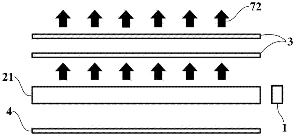
[0033] Figure 2(a) , 2(b) and 2(c) show the side-lit backlight.

[0034] The light guide cavity 5 is a hollow cylinder with a rectangular cross section. The incident light 7 is obliquely incident into the cavity from the incident surface at one end of the light guide cavity 5, and the light inside the light guide cavity 5 overflows into a linear shape from the light exit surface, so that the incident light 7 can be converted into a quasi-continuous line light source; The continuous line light source is coupled into the light guide plate 21 from one side of the light guide plate 21, and the light guide plate 21 converts the incident line light source into a surface light source.

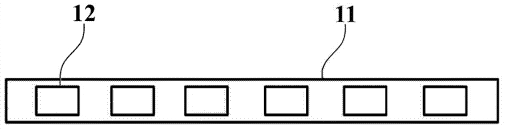
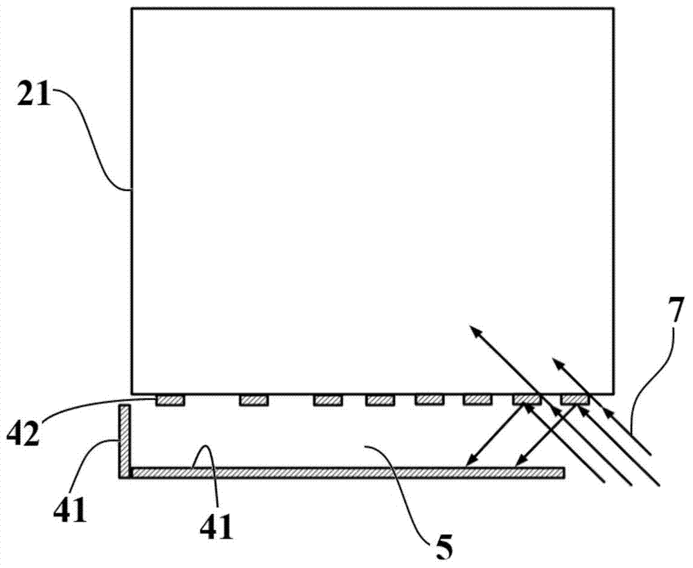
[0035] The light guide cavity 5 is pasted with a reflective film as the reflective layer of the light guide cavity 5 except the incident surface, wherein the light emitting surface is pasted with a discrete reflective film 42, and the other faces are pasted with a continuous reflective film 41, and...

Embodiment 2

[0038] image 3 Shown is a double-beam incident structure, and the difference from Embodiment 1 is that the incident light 7 is incident from both ends of the light guide cavity 5, and the incident surfaces are two end surfaces.

[0039] The discrete reflective film 42 on the light exit surface of the light guide cavity 5 is directly attached to the side of the light guide plate 21, and the light guide plate 21 is used as a support structure for the reflective film.

[0040] The reflective film uses a semi-transparent and semi-reflective film, and the reflection method can be selected from specular reflection or diffuse reflection.

Embodiment 3

[0042] Figure 4(a) and 4(b) Shown is a direct-type backlight, and Figure 4(b) is the structure of Figure 4(a) turned 90° horizontally.

[0043] The light guide cavity 5 is a flat hollow structure, including top, bottom and side surfaces; the incident light 7 of the direct-type backlight is different from that of the side-type backlight. Simultaneous oblique incidence, the two opposite sides are incident surfaces; the top surface is the light-emitting surface, which is a transparent substrate 6 with a discrete reflective film 42 attached, the transparent substrate 6 does not absorb visible light, and plexiglass material can be used; obliquely incident light Reflected by the discrete reflection film 42 on the light exit surface, it becomes reflected light 70 , and part of it passes through the transparent substrate 6 to become transmitted light 71 .


PUM


Abstract

A liquid crystal display laser backlight source comprises a side incident mode structure and a direct down mode structure. A light guide cavity of the side incident type backlight source is cylindrical and comprises a cylindrical face and two end faces; incident light obliquely enters from the end faces, and the end faces are incident faces; the cylindrical face on one side is a light emerging face, and light in the cavity overflows from the light emerging face and is coupled into a light guide plate from the side face and emerges out to form backlight. A light guide cavity of the direct down mode backlight source is platy and comprises a top face, a bottom face and side faces. Multiple beams of incident light simultaneously and obliquely enters from the two opposite side faces of the light guide cavity, and the incident side faces are incident faces; the top face of the light guide cavity is a light emerging face, light in the cavity overflows out of the liquid emerging face and then enters a diffusion plate from the bottom face to be diffused and emerges to form backlight. Discrete reflecting layers are arranged on the light emerging face, the light in the cavity overflows out of gaps of the reflecting layers of the light emerging face, the distribution density of the discrete reflecting layers is changed along with the distances to the incident faces, and the shorter the distances are, the denser the reflecting layers are. The backlight source is simple in structure and low in cost, and light intensity distribution is evener.

Description

technical field [0001] The invention relates to the technical field of liquid crystal display, in particular to a liquid crystal display backlight with laser as a light source, and the structure of the backlight includes a side-in type and a direct-down type. Background technique [0002] The backlight source is an important part of the liquid crystal display device. Since the liquid crystal molecules themselves do not emit light, additional equipment is needed to provide it with a light source. Most of the current backlight light sources are LED light sources. As shown in Figure 1(a), it is a commonly used side-type backlight structure. There is an incident line light source 1 on the side of the light guide plate, and the light of the incident line light source 1 is coupled to A surface light source is formed in the light guide plate 21; a reflective layer 4 is provided under the light guide plate 21 to reflect stray light and improve the utilization efficiency of light; an...

Claims


Application Information

Patent Timeline
IPC IPC(8): F21S8/00F21V8/00F21V7/22G02F1/13357F21Y101/02F21Y115/10
CPCG02F1/133605G02F1/133606G02F1/133615G02F1/133607
Inventor 王欢陈昱
Owner NANJING MAGICSKY AVIATION TECH
Features
  • R&D
  • Intellectual Property
  • Life Sciences
  • Materials
  • Tech Scout
  • Unparalleled Data Quality
  • Higher Quality Content
  • 60% Fewer Hallucinations
Learn More