
Core type elevator furnace

A bell furnace and core type technology, which is applied to the heating of bell furnaces, furnaces, electric furnaces, etc., can solve the problems of high failure rate, inability to shorten the temperature rise, heat preservation time, and saw blades cannot effectively receive heat sources, etc.

Inactive Publication Date: 2015-07-08
河北小蜜蜂工具集团有限公司
View PDF5 Cites 1 Cited by
  • Summary
  • Abstract
  • Description
  • Claims
  • Application Information

AI Technical Summary

Problems solved by technology

The bell furnace is heated by the peripheral furnace wire, and the saw blades are gathered in the middle area in the form of a circle. This distribution makes the saw blades in the central area unable to effectively receive the heat source, while the peripheral saw blades receive a large amount of heat source, resulting in uneven sintering. exogenous over endogenous phenomenon
In order to mature the sintering of the saw blade in the central area, longer heating time and holding time are required. Too long heating time will cause waste of electric energy and low production efficiency
[0003] Aiming at the defects of slow heat conduction rate, long heating time, low production efficiency and high failure rate of bell furnace
Competitors at home and abroad have worked hard on the improvement of the bell furnace. South Korea adopts the method of obliquely injecting hydrogen gas, but the effect is not ideal, but to a certain extent, the protective effect of the protective gas on the saw blade is strengthened; domestic counterparts use the base to rotate The bell furnace can effectively improve the protection of the protective gas on the saw blade, but it cannot shorten the heating and holding time

Method used


Image

  • Core type elevator furnace
  • Core type elevator furnace

Examples


Embodiment Construction

[0017] In order to deepen the understanding of the present invention, the present invention will be described in further detail below in conjunction with the accompanying drawings and embodiments, which are only used to explain the present invention and do not limit the scope of protection.

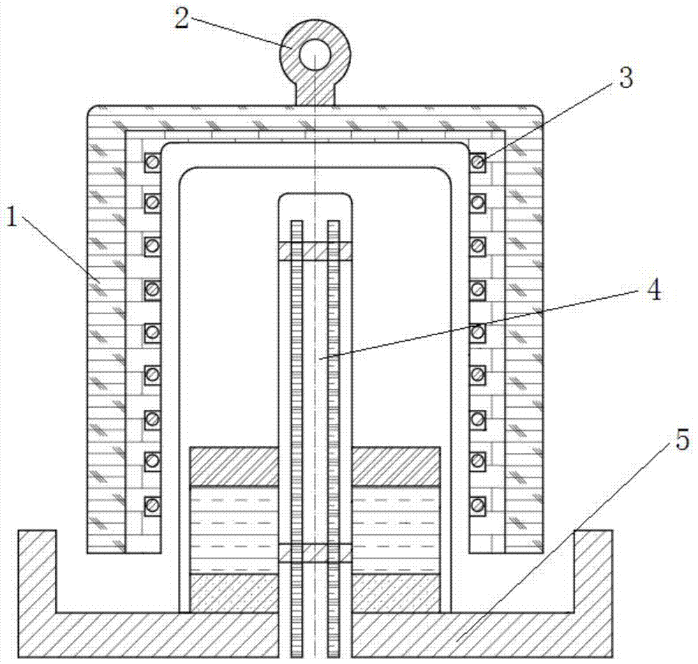
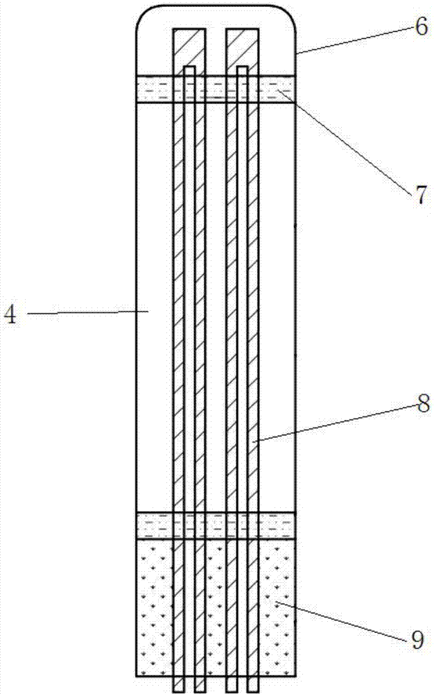
[0018] A core-type bell furnace provided in this embodiment includes an outer cover 1 with heating elements 3 symmetrically arranged on the inner wall, a base 5, 3-6 U-shaped silicon carbide rods 8, an inner container 6, and a refractory ceramic fixture 7 1. A central heating rod 4 composed of asbestos 9; the central heating rod 4 is fixed at the center of the base 5. The central heating rod 4 and the outer cover 1 are directly and vertically connected with the base 5 . The U-shaped silicon carbide rod 8 is fixed in the inner tank 6 by the refractory ceramic fixture 7; the root of the inner tank 6 is filled with asbestos 9 . The central heating rod power is 10-30KW. Core type bell furna...


PUM


Abstract

The invention discloses a core type elevator furnace, and specifically relates to the technical field of thermal treatment processing equipment. The core type elevator furnace comprises an outer cover (1), and a base (5); the core type elevator furnace further comprises a central heating stick (4); the central heating stick (4) is fixed in the center of the base (5). The core type elevator furnace employs the central and peripheral concentric circles to heat synchronously, with the outer cover being a main heat source and the central heating stick being a supplementary heat source. Saw blades are distributed in a circular zone between the inner heat source and the outer heat source, thus the saw blades are equidistantly located from the heat sources, accordingly the heat radiation efficiency is high, the heat transmission efficiency is high, the heating speed is fast, and the hearth temperature is uniform. Heating by such manners, the phenomenon of over-heating the outer sides whereas under-heating the inner sides of the saw blades can be avoided effectively. Due to the fact that the temperature is uniform, the product is uniformly heated, the alloying degree of the cutter head is high, and the quality and performance of the product are increased.

Description

technical field [0001] The invention belongs to the technical field of heat treatment processing equipment, and in particular relates to a core-type bell furnace. Background technique [0002] At present, the heat sources required in the production process of domestic diamond tools are resistance furnaces, pit furnaces, continuous furnaces, and bell furnaces, among which continuous furnaces and bell furnaces are widely used. The bell furnace is heated by the peripheral furnace wire, and the saw blades are gathered in the middle area in the form of a circle. This distribution makes the saw blades in the central area unable to effectively receive the heat source, while the peripheral saw blades receive a large amount of heat source, resulting in uneven sintering. Exogenous over endogenous phenomenon occurs. In order to mature the sintering of the saw blade in the central area, longer heating time and holding time are required. Too long heating time causes waste of electric en...

Claims


Application Information

Patent Timeline
IPC IPC(8): F27B11/00F27D11/02
Inventor 曹雄志董小雷曾柳彭乃聪魏娅婷张乐
Owner 河北小蜜蜂工具集团有限公司
Learn More