
Pulsed eddy current infrared thermal imaging detection system and method for steel rail cracks

A technology of infrared thermal imaging and pulsed eddy current, which is applied in the direction of material defect testing, etc., can solve the problems that the test results are easily affected by human factors, cannot reflect cracks in detail, and the image resolution is not large enough to achieve convenient and intuitive detection means, The effect of saving manpower and accurate experimental results

Inactive Publication Date: 2015-07-08
NANJING UNIV OF AERONAUTICS & ASTRONAUTICS
View PDF11 Cites 69 Cited by
  • Summary
  • Abstract
  • Description
  • Claims
  • Application Information

AI Technical Summary

Problems solved by technology

The detection system has the following defects: 1. The excitation source used is a high-frequency excitation source. Although it has a high excitation frequency, its excitation power is insufficient and the detection efficiency is low; 2. The acquisition frequency of the infrared thermal imager used Only 50Hz, the image resolution is not large enough to reflect some details of the crack in detail; 3. The excitation source and the excitation of the infrared thermal imaging camera are performed manually separately, and the detection results are easily affected by human factors

Method used

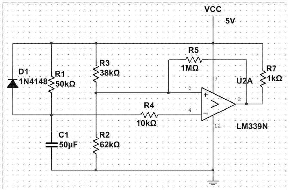
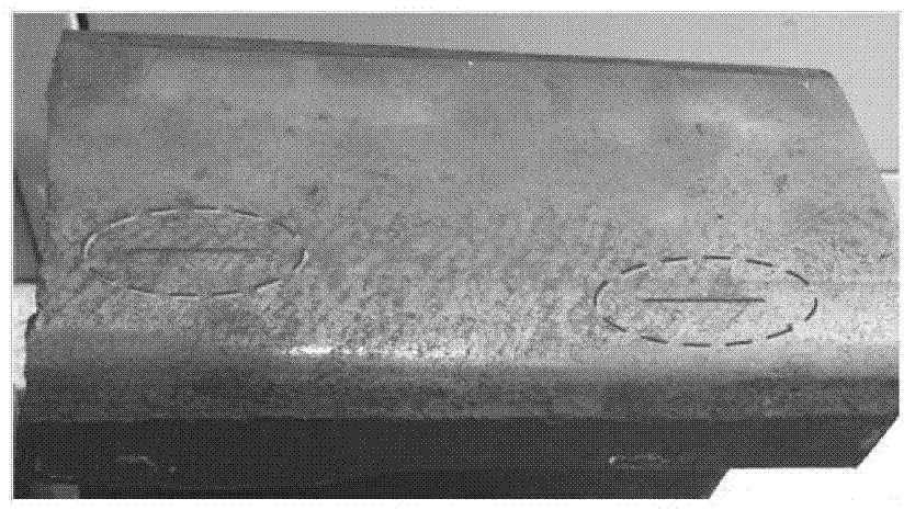

Image

  • Pulsed eddy current infrared thermal imaging detection system and method for steel rail cracks
  • Pulsed eddy current infrared thermal imaging detection system and method for steel rail cracks
  • Pulsed eddy current infrared thermal imaging detection system and method for steel rail cracks

Examples


Embodiment Construction

[0026] The present invention will be described in further detail below in conjunction with the accompanying drawings.

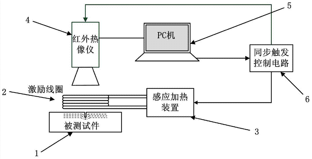
[0027] like figure 1 As shown, a pulsed eddy current infrared thermal imaging detection system of a rail crack of the present invention includes: an excitation device (2), an induction heating device (3), an infrared thermal imager (4), a PC (5); The induction heating device (3) is used to generate a pulse current signal, which is applied to the test piece (1) through the excitation device (2); the eddy current is induced inside the surface of the test piece (1) and produces a thermal effect Make the surface temperature distribution change; the infrared thermal imaging camera (4) is used to record the surface temperature change process of the described tested piece (1) and transmit it to the PC for processing and analysis, and it is characterized in that: it also includes synchronous The trigger control circuit (6) is used to synchronously control the excita...


PUM


Abstract

The invention discloses a pulsed eddy current infrared thermal imaging detection system and method for steel rail cracks. The system comprises an excitation device, an induction heating device, an infrared thermal imager and a PC, wherein the induction heating device is used for generating a pulse current signal; the pulse current signal is exerted to a tested part through the excitation device; eddy current is induced from the surface of the tested part and a thermal effect is generated, so that the surface temperature distribution changes; the infrared thermal imager is used for recording the surface temperature change process of the tested part and transmitting to the PC to process and analyze. The pulsed eddy current infrared thermal imaging detection system is characterized by also comprising a synchronous trigger control circuit, which is used for synchronously controlling the excitation and recording time of the induction heating device and the infrared thermal imager, so that the heating and cooling processes after complete induction of the tested part are accurately recorded; and the condition that the PC obtains accurate data to analyze and treat is ensured. The pulsed eddy current infrared thermal imaging detection system is high in detection efficiency and high in image resolution ratio; excitation of an excitation source and the infrared thermal imager can be synchronously carried out; and the detection result is not affected by human factors.

Description

technical field [0001] The invention belongs to the technical field of non-destructive testing, and in particular relates to a pulsed eddy current infrared thermal imaging detection system and a method for rail cracks. Background technique [0002] Railway transportation is the main transportation mode of land transportation in the world today. As an important part of railway, the quality inspection of steel rail is very important. During the operation of high-speed trains, when the train speed reaches a certain value, the degree of rail wear decreases, and the contact surface between the wheel tread and the inner side of the top surface of the rail is the main stress-bearing part, and the final defect form is mainly rolling contact fatigue damage, which is the most important. A structural defect. When the train wheel repeatedly acts on the surface of the rail, the internal structure of the material will change due to the cyclic effect of tension and compression stress, and ...

Claims


Application Information

Patent Timeline
IPC IPC(8): G01N25/72
Inventor 王平焦婷李东林洋吴杰
Owner NANJING UNIV OF AERONAUTICS & ASTRONAUTICS
Learn More