Cathode emitter

A cathode emission and emitter technology, which is applied in the direction of cathode ray tube/electron beam tube, thermal electron cathode, electron emission electrode/cathode, etc. It can solve the problems that affect the emission life, the emitter cannot meet the long life, and the emission performance is reduced.

Inactive Publication Date: 2015-07-08
CHENGDU GUOGUANG ELECTRIC
View PDF8 Cites 0 Cited by
  • Summary
  • Abstract
  • Description
  • Claims
  • Application Information

AI Technical Summary

Problems solved by technology

In some electronic devices, such as the Hall thruster, when the emitter is working, the emitter is first heated slowly. When the temperature of the emitter reaches the emission temperature, the emitter generates enough hot electrons, which are used to ionize the neutral gas entering the cathode tube. , add the ignition voltage to the control pole, so that the ions move to the emitter and bombard the emitter, maintain the temperature of the emitter, then turn off the power, and enter the self-sustained discharge state. At this time, the cathode emitter is in a high-temperature working state, causing the cathode to work for a long time The post-launch performance will be reduced, which will affect the launch life; and as some electronic devices that need to work for a long time, such as the electric propulsion Hall thruster, the service life is required to reach at least 8000 hours, and the current existing emitters cannot meet the long-life requirements. Require

Method used


Image

  • Cathode emitter
  • Cathode emitter

Examples


Embodiment Construction

[0012] The present invention will be further described below in conjunction with drawings and embodiments.

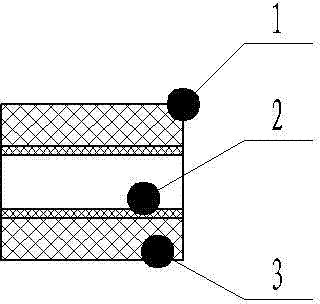
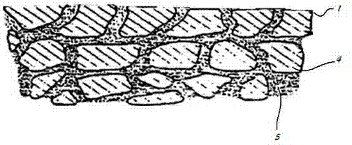
[0013] This embodiment provides a cathode emitter whose structure is as follows figure 1 As shown, the enlarged structure diagram is shown in figure 2 As shown, the cathode emitter described in this embodiment includes an emission matrix made of tungsten material and an aluminate impregnation, the emission matrix has pores, and the impregnation aluminate is placed in the pores of the emitter, the The pores of the emission matrix have different pore sizes, and the pore size of the pores on the working surface of the emission matrix is ​​smaller than that of other parts of the emission matrix. In this embodiment, the cathode emitter is a hollow tube in the middle. The structure includes an inner emitter layer and an outer emitter layer from the inside to the outside, the working surface of the cathode emitter is the surface of the inner layer, and the pores of the emit...


PUM


Abstract

The invention discloses a cathode emitter comprising an emitting matrix and impregnant. The emitting matrix is provided with holes, and the impregnant is arranged in the holes of the emitting matrix. The holes of the emitting matrix have different apertures. The apertures of the holes in the work face of the emitting matrix are smaller than those of the holes in other parts of the emitting matrix. Under the condition that an emitting current is 4.5-5 A and the number of times of thermal cycle impact reaches 10000, the normal service life of the cathode emitter is longer than 10000 hours.

Description

technical field [0001] The invention relates to a cathode, in particular to a hot cathode. Background technique [0002] Cathode is widely used in many electronic devices, is the source of electron emission in electronic devices, and is an important part of electronic devices. In some electronic devices, such as the Hall thruster, when the emitter is working, the emitter is slowly heated. When the temperature of the emitter reaches the emission temperature, the emitter generates enough hot electrons, which are used to ionize the neutral gas entering the cathode tube. , add the ignition voltage to the control pole, so that the ions move to the emitter to bombard the emitter, maintain the temperature of the emitter, then turn off the power, and enter the self-sustained discharge state. At this time, the cathode emitter is in a high temperature working state, causing the cathode to work for a long time The post-launch performance will be reduced, which will affect the launch ...

Claims


Application Information

Patent Timeline
Patent Type & Authority Applications(China)
IPC IPC(8): H01J19/04H01J29/04H01J1/13
Inventor 唐海宸
Owner CHENGDU GUOGUANG ELECTRIC
Why Eureka
Try Eureka