Navigation device for bone block directional movement in orthognathic surgery and manufacturing method thereof

A technology of surgical operation and navigation device, which is applied in the fields of surgery, application, medical science, etc., and can solve problems such as trauma of patients, difficulties in ensuring complete fit of retention splints, and increased operating procedures.

Active Publication Date: 2015-07-15
SICHUAN UNIV
View PDF9 Cites 25 Cited by
  • Summary
  • Abstract
  • Description
  • Claims
  • Application Information

AI Technical Summary

Problems solved by technology

Although this kind of intermediate guide plate can accurately locate the position of the maxillary bone fragment before the bone fragment is fixed, there are the following problems: after using the intermediate guide plate to locate the maxillary bone fragment and moving to the target position, the surgeon needs to select and place the retention splint by himself , so the shape of the retention splint is difficult to ensure a complete fit with the bone surface, which affects the stability of the position of the bone block; the fixation of the small positioning plate needs to drill holes in the bone surface, and the installation of the retention splint also needs to drill holes in the bone surface, so it will be difficult for the patient. Additional trauma and increased procedures

Method used


Image

  • Navigation device for bone block directional movement in orthognathic surgery and manufacturing method thereof
  • Navigation device for bone block directional movement in orthognathic surgery and manufacturing method thereof
  • Navigation device for bone block directional movement in orthognathic surgery and manufacturing method thereof

Examples


Embodiment 1

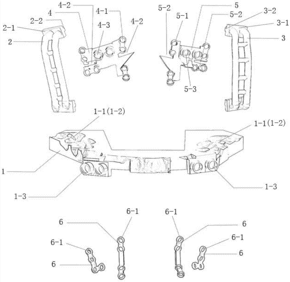
[0070] The structure of the navigation device used for the directional movement of the maxillary block in orthognathic surgery described in this embodiment is as follows: figure 1 As shown, the U-shaped occlusal plate 1, the maxillary left navigation plate 4 matching the maxillary left bone surface, the maxillary right navigation plate 5 matching the maxillary right bone surface, and the U-shaped occlusal plate connected with the maxillary left The maxillary left connecting piece of the side navigation board 2, the maxillary right connecting piece connecting the U-shaped occlusal plate and the maxillary right navigation board 3, used for moving and navigating the maxillary bone fragments and fixing the moved maxillary bone fragments Four maxillary bone retention splints 6 are composed; the thickness of the U-shaped occlusal plate 1 is 4mm, and its upper surface and lower surface are respectively provided with upper dentition imprints 1-1 matched with the occlusal surface of the...

Embodiment 2

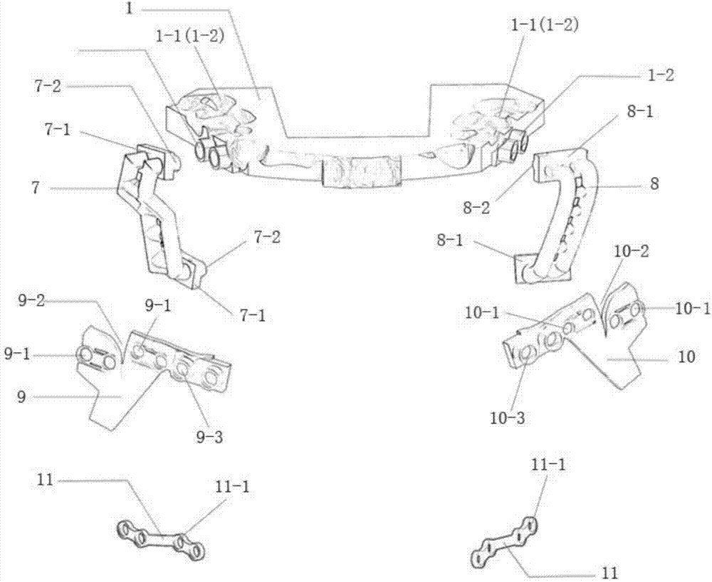
[0084] The structure of the navigation device used for the directional movement of the mandibular block in orthognathic surgery described in this embodiment is as follows: figure 2 As shown, a U-shaped occlusal plate 1, a mandibular left navigation plate 9 matching the maxillary left bone surface, a mandibular right navigation plate 10 matching the mandibular right bone surface, and a U-shaped occlusal plate connected to the maxillary left The mandibular left connecting piece 7 of the side navigation board, the maxillary right connecting piece 8 connecting the U-shaped occlusal plate and the maxillary right navigation board, used for moving and navigating the mandibular bone fragments and fixing the mandibular bone fragments moved in place It consists of two mandibular bone retention splints 11; the thickness of the U-shaped occlusal plate 1 is 4mm, and its upper surface and lower surface are respectively provided with upper dentition marks 1-1 matching with the occlusal surfa...

Embodiment 3

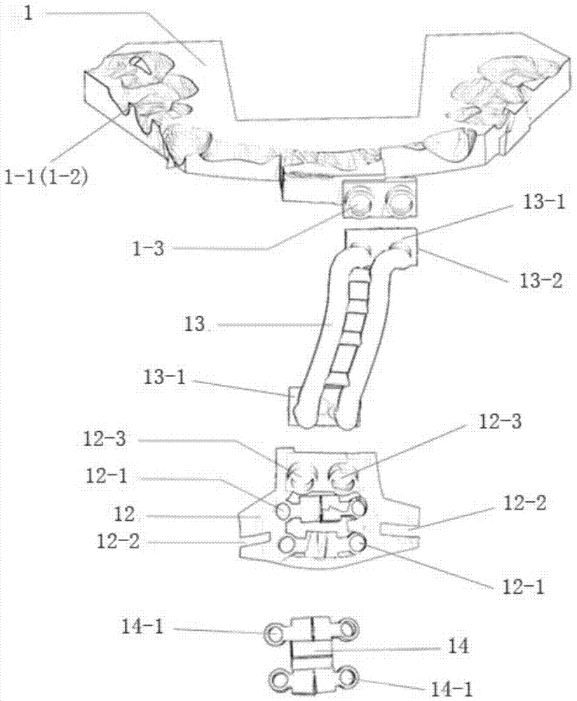
[0098] The structure of the navigation device used for the directional movement of the chin bone in orthognathic surgery described in this embodiment is as follows: image 3 As shown, a U-shaped occlusal plate 1, a chin navigation plate 12 matching the front bone surface of the mandible, a chin connector 13 connecting the U-shaped occlusal plate and the chin navigation plate are used for moving and navigating the chin bones. and a chin retaining splint 14 that fixes the chin bone that has moved into place; the thickness of the U-shaped occlusal plate 1 is 4mm, and its upper surface and lower surface are respectively provided with an occlusal surface with the upper dentition The matching upper dentition imprint 1-1, the lower dentition imprint 1-2 matching the occlusal surface of the lower dentition, the depth of the upper and lower dentition imprints is 2mm, and the end surface of the U-shaped occlusal plate is provided with a joint that is combined with the connecting piece S...


PUM


Abstract

The invention relates to a navigation device for bone block directional movement in an orthognathic surgery. The navigation device for bone block directional movement in the orthognathic surgery comprises a U-shaped occluding plate; an upper jaw left navigation plate and an upper jaw right navigation plate, a lower jaw left navigation plate and a lower jaw right navigation plate or a chin navigation plate; an upper jaw left connecting piece and an upper jaw right connecting piece, a lower jaw left connecting piece and a lower jaw right connecting piece or a chin connecting piece; at least two upper jaw fixing splints which are used for navigating upper jaw bone block movement during the surgery and fixing an upper jaw bone block which is moved in place, at least two lower jaw fixing splints which are used for navigating lower jaw bone block movement and fixing a lower jaw bone block which is moved in place, or at least one chin fixing splint which is used for navigating chin bone block movement and fixing a chin bone block which is moved in place. The components are designed through software and are manufactured by adopting a quick forming method.

Description

technical field [0001] The invention belongs to the field of auxiliary medical devices, and in particular relates to a navigation device for directional movement of bone blocks in orthognathic surgery and a manufacturing method thereof. Background technique [0002] Orthognathic surgery improves craniofacial deformities by separating the maxilla, mandible, and / or chin parts and moving them to the target position. Traditional orthognathic surgery uses an occlusal occlusal splint as a moving and positioning tool for bone fragments, but its fabrication process is complicated. Because it is difficult to ensure the stability of the mandibular condyle in the glenoid fossa during the operation, and the traditional occlusal splint is positioned according to the occlusal position of the dentition, it cannot guarantee the relative position between the bone blocks, and there is a large error in the moving position of the bone blocks. [0003] Patent CN201420093818.8 discloses "an inte...

Claims


Application Information

Patent Timeline
Patent Type & Authority Applications(China)
IPC IPC(8): A61B19/00A61B17/56
CPCA61B17/56A61B2017/564
Inventor 薛超然白丁罗恩杜文舒睿
Owner SICHUAN UNIV
Why Eureka
Try Eureka