Mechanical arm kinematics formal analysis method

An analysis method and a technology of a manipulator, applied in the field of manipulators, can solve problems such as inaccurate results and complex calculations

Active Publication Date: 2015-07-15
CAPITAL NORMAL UNIVERSITY
View PDF1 Cites 19 Cited by
  • Summary
  • Abstract
  • Description
  • Claims
  • Application Information

AI Technical Summary

Problems solved by technology

[0004] In view of this, the purpose of the present invention is to provide a formal analysis method of ...

Method used


Image

  • Mechanical arm kinematics formal analysis method
  • Mechanical arm kinematics formal analysis method
  • Mechanical arm kinematics formal analysis method

Examples


Embodiment 1

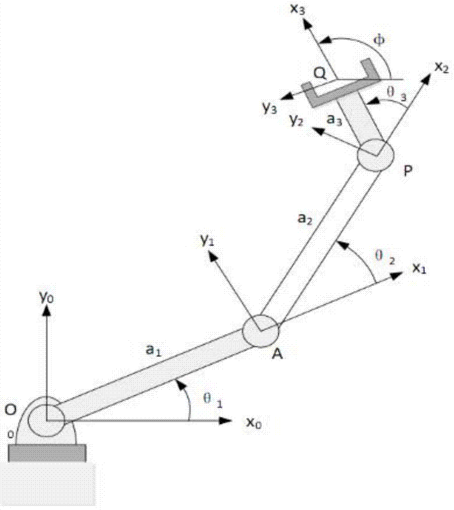
[0121] In this embodiment, the formalized analysis method of the kinematics of the manipulator in this application is specifically described by taking a plane 3-DOF manipulator as an example.

[0122] Such as figure 1 The D-H parameters of the shown planar 3-DOF manipulator are shown in Table 1:

[0123] Table 1 D-H parameters of the planar 3-DOF manipulator

[0124] the joint

α i

a i

d i

θ i

1

0

a 1

a 1

θ 1

2

0

a 2

a 2

θ 2

3

0

a 3

a 3

θ 3

[0125] In Table 1, α i Indicates the torsion angle between the rotation axes of each revolving pair, a i Indicates the offset distance (connecting rod length) between two adjacent revolving pairs, d i Indicates the distance between the vertical feet of the common normal between the rotation axes of two adjacent revolving pairs, θ i Indicates the angle of rotation of the revolving joint.

[0126] Determine the screw coordinates...

Embodiment 2

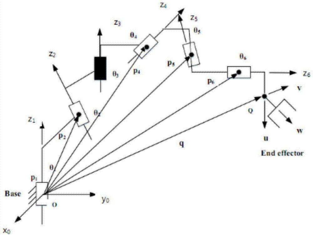
[0182] In this embodiment, a singular configuration of a 6R robot is used for judgment

[0183] image 3 It shows a state diagram of a 6R robot in a singular configuration, in which the black-marked rotary joint is in a singular configuration, and the mechanism has the following special parameters:

[0184] the joint

z i

θ i

d i

1

(0,0,1) T

any angle

1

2

(0,1,0) T

0

1

3

(0,0,1) T

any angle

1

4

Take any

any angle

1

5

Take any

any angle

1

6

Take any

any angle

1

[0185] Table 2 A singular configuration parameter of the 6R robot

[0186] Table 2, z i respectively represent the rotation axes of each joint of the mechanism, θ i Indicates the rotation angle of each joint of the mechanism, d i Indicates the connecting rod length.

[0187]

[0188] in, represents the primordial part of the spinor, Represents the even part of the sc...


PUM


Abstract

The invention relates to a mechanical arm kinematics formal analysis method. The method comprises the steps of 1, determining structural parameters of a mechanical arm mechanism; 2, using high-order logical language for building a mechanical arm kinematics logical model; 3, using a logical formula for describing kinematics constraints or attributes needing to be verified; 4, enabling the mechanical arm mechanism kinematics logical model and the kinematics constraints or attributes needing to be verified to form a logical proposition; 5, utilizing a logical reasoning engine for proving whether the logical proposition is true or not; if the logical proposition is true, it represents that the model meets the kinematics constraints or have the attributes; if not, it represents that the model does not meet the kinematics constraints or does not have the attributes. According to formal verification, on the basis of system formal specifications or attributes, the correctness of the system is verified by using the mathematical method, and the verified attributes are precise and complete.

Description

technical field [0001] The invention relates to the technical field of manipulators, in particular to a formalized analysis method for the kinematics of a manipulator. Background technique [0002] In recent years, robotic arm technology has entered a period of rapid development. Robots with mechanical arms are widely used in various fields such as industry, scientific investigation, military, emergency rescue, medical treatment and household use. However, it is not uncommon for robots to fail or even have safety accidents when performing tasks. It is recognized that there is a significant gap between the verification technology of the robot and the design technology. A small loophole in the robot design may cause huge economic losses and even endanger personal safety. Therefore, designers must spend a lot of time and energy analyzing and verifying the design in order to find errors in the robot design before the product is formed. [0003] At present, the commonly used ve...

Claims


Application Information

Patent Timeline
IPC IPC(8): B25J19/00
Inventor 施智平关永吴爱轩李黎明李晓娟王瑞邵振洲张倩颖吴敏华
Owner CAPITAL NORMAL UNIVERSITY
Why Eureka
Try Eureka