
Automotive seat slide rail

A technology of sliding rails and sliding rails for automobile seats, which is applied in the direction of movable seats, etc., to achieve the effects of easy assembly, simple structure of the sliding rails, and good quality control.

Active Publication Date: 2015-07-15
KEIPER (CHANGSHU) SEATING MECHANISMS CO LTD
View PDF8 Cites 16 Cited by
  • Summary
  • Abstract
  • Description
  • Claims
  • Application Information

AI Technical Summary

Problems solved by technology

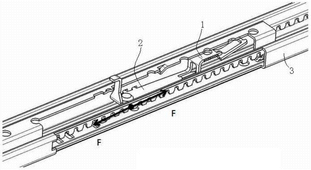
[0004] The technical problem to be solved by the present invention is to provide a car seat slide rail with fewer parts in the locking system and a smaller comprehensive tolerance after assembly in view of the above-mentioned technical problems existing in the existing seat slide rail.

Method used


Image

  • Automotive seat slide rail
  • Automotive seat slide rail
  • Automotive seat slide rail

Examples


Embodiment 1

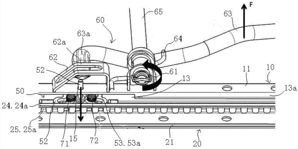
[0091] see Figure 3 to Figure 8 , the car seat slide rail given in the figure includes an upper slide rail 10, a lower slide rail 20, a spring component, a locking component 50 and an unlocking component.

[0092] See especially Figure 7 and Figure 8 , the upper slide rail 10 has an upper wall portion 11 connected to the seat cushion frame (not shown in the figure) and two outer flanges 12, 12a and two inner flanges 13, 13a, the two inner flanges 13, 13a of the upper slide rail 10 are formed by folding down from both sides of the upper wall portion 11, and the two outer flanges 12, 12a of the upper slide rail 10 are respectively formed by the two sides of the upper slide rail 10. The bottoms of the strip inner flanges 13, 13a are folded outwards and upwards. Four upper teeth windows 14, 14a are respectively configured on the two inner flanges 13, 13a of the upper slide rail 10 (in conjunction with referring to Figure 4 , Figure 6 ).

[0093] See also in particular ...

Embodiment 2

[0104] see Figure 11 , the car seat slide rail shown in the figure includes an upper slide rail 100 , a lower slide rail 200 , a spring component 300 , a locking component 400 and an unlocking component 500 .

[0105] see in conjunction Figure 12 , Figure 13 , Figure 16 and Figure 17 , the upper slide rail 100 has an upper wall portion 110 connected to the seat cushion frame (not shown in the figure) and two outward turning edges 120, 120a and two inner turning edges 130, 130a, the two inner flanges 130, 130a of the upper slide rail 100 are formed by folding down from both sides of the upper wall portion 110, and the two outer flanges 120, 120a of the upper slide rail 100 are respectively formed by the two sides of the upper slide rail 100. The bottoms of the strip inner flanges 130, 130a are folded outwards and upwards. Four upper teeth windows 140 , 140 a are respectively arranged on the two inner flanges 130 , 130 a of the upper slide rail 100 . In addition, on t...

Embodiment 3

[0122] Except that the structure of the upper wall part 110 in the upper slide rail 100 is slightly different from that of Embodiment 2 and the spring part is slightly different in the car seat slide rail of this embodiment, and the installation part 310 of the spring part is different from the upper wall part 100 of the upper slide rail 100. Except for the installation method of the wall part 110, the remaining parts are the same as in the second embodiment.

[0123] Only the differences between this embodiment and Embodiment 2 will be described below, and for the similarities, refer to the relevant description of Embodiment 2.

[0124] see Figure 50 and 51 , the spring part 300' of this embodiment is a special-shaped spring part, and the special-shaped spring part has a mounting part 310', elastic parts 320', 330', and the elastic part 320' is hollowed out and connected with the mounting part 310'. The junction begins to extend outward in waves.

[0125] The elastic part...


PUM


Abstract

The invention discloses an automotive seat slide rail. The automotive seat slide rail comprises an upper slide rail body, a lower slide rail body, a spring component, a locking component and an unlocking component, wherein the unlocking component drives the locking component to move up and down to achieve locking and unlocking of the upper slide rail body and the lower slide rail body, the locking component comprises a locking sheet and a guide pin, locking tooth parts are arranged on the two sides of the locking sheet, the lower end of the guide pin is connected with the locking sheet in an anchoring mode, and the upper portion of the guide pin penetrates through a guide pin hole in the upper wall of the upper slide rail body; the spring component acts on the space between the locking sheet and the upper wall of the upper slide rail body or the space between the locking sheet and the lower wall of the lower slide rail body; when the upper slide rail body and the lower slide rail body are in a locked state, the locking tooth parts penetrate through an upper tooth window on the upper slide rail body and a lower tooth window on the lower slide rail body; when the upper slide rail body and the lower slide rail body are in an unlocked state, the locking tooth parts disengage from the lower tooth window on the lower slide rail body. According to the automotive seat slide rail, structure becomes simpler, assembly becomes easily, quality control is facilitated, cost is reduced, the weight of the whole slide rail is reduced, and the stress on the spring component from the slide rail in long-time use is effectively eliminated.

Description

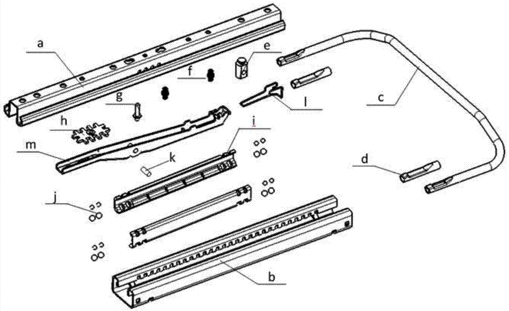
technical field [0001] The invention relates to the technical field of car seats, in particular to a car seat slide rail. Background technique [0002] see figure 1 , the seat slide rails currently on the market include upper slide rail a, lower slide rail b, locking plate h, locking connecting member m, return spring l, two steel ball cages i and four sets of upper and lower balls j , the upper and lower sets of balls j are installed on two steel ball cages i to form a pair of slider assemblies, the upper slide rail a slides on the lower rail b by relying on a pair of slider assemblies, and the locking connecting member m is groove type structure, the middle positions of the two groove walls are respectively provided with a shaft hole, and the locking connection member m is installed on a shaft seat e through the shaft k passing through the shaft hole, and the shaft k also passes through the shaft seat e at the same time, and the shaft seat e is installed On the upper sli...

Claims


Application Information

Patent Timeline
IPC IPC(8): B60N2/08
CPCB60N2/08
Inventor 倪洪斌陈新鹏刘东唐臻毅
Owner KEIPER (CHANGSHU) SEATING MECHANISMS CO LTD
Learn More