Elevator traction system

An elevator traction and traction technology, applied in the field of elevators, can solve the problems of unfavorable elevator traction system hoistway layout, high performance requirements of the traction main engine, inconvenient installation and maintenance, etc., so as to achieve convenient hoistway installation and maintenance and convenient hoistway layout. , the effect of improving work efficiency

Active Publication Date: 2015-07-15
HITACHI ELEVATOR CHINA
View PDF6 Cites 2 Cited by
  • Summary
  • Abstract
  • Description
  • Claims
  • Application Information

AI Technical Summary

Problems solved by technology

In this way, the performance requirements for the traction main engine are high, and the cost is increased, which is not conducive to energy saving and environmental protection, and is not conducive to the well layout of the elevator traction system
[0005] 2. The positions of the traction main engine, the counterweight rope ends used to fix the ends of the pull ropes, and the car rope ends are scattered, and are prone to failures, making installation and maintenance extremely inconvenient

Method used


Image

  • Elevator traction system
  • Elevator traction system
  • Elevator traction system

Examples


Embodiment 1

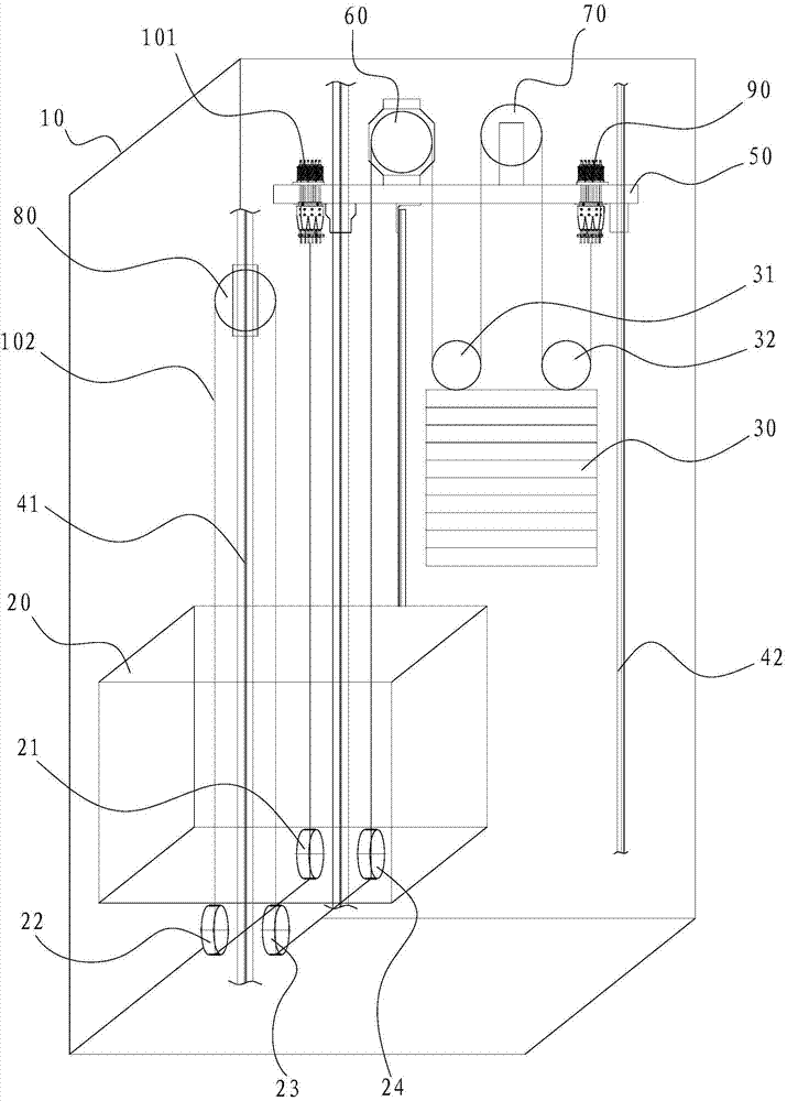
[0036] Such as figure 1As shown, the elevator traction system of the present invention includes: the hoistway 10, the car guide rail 41 and the counterweight guide rail 42, the car 20, the counterweight 30, the traction host 60, the installation beam 50, and the counterweight rope head 90 , car rope end 101, counterweight side guide wheel 70 and car side guide wheel 80, stay rope 102; Described car guide rail 41 is two to form a pair, and described counterweight guide rail 42 also is two to form a pair Yes, the car guide rail 41 and the counterweight guide rail 42 are respectively arranged in the hoistway 10, the car 20 is arranged in the hoistway 10 and guided by the car guide rail 41, in the The car 20 is provided with a car pulley one 21, a car pulley two 22, a car pulley three 23 and a car pulley four 24; the counterweight 30 is arranged in the hoistway 10 and is guided by the counterweight guide rail 42 for guiding, and the counterweight 30 is provided with a counterweig...

Embodiment 2

[0041] see Figure 4 , looking down from the hoistway 10, the counterweight-side guide wheel 70 is arranged obliquely relative to the traction sheave 61, and the two ends of the counterweight-side guide wheel 70 respectively protrude from both sides of the installation beam 50; The traction sheave 61 and the counterweight rope end 90 protrude from both sides of the installation beam 50 respectively, and the counterweight pulley 1 31 and the counterweight pulley 2 32 are located on both sides of the installation beam 50 respectively. side, the two ends of the counterweight side guide wheel 70 overlap with one end of the counterweight pulley one 31 and one end of the counterweight pulley two 32 respectively, and the other end of the counterweight pulley one 31 and the counterweight The other end of the second pulley 32 overlaps with one end of the counterweight rope end 90 and the traction sheave 61 respectively. Specifically, the traction sheave 61 and the installation beam 50...

Embodiment 3

[0043] see Figure 7 , looking down from the hoistway 10, the traction sheave 61 and the counterweight rope end 90 protrude from the same side of the installation beam 50, and the counterweight side guide wheel 70 is opposite to the traction main machine 60 is farther away from the car 20, the first counterweight pulley 31 and the second counterweight pulley 32 are inclined relative to the installation beam 50, and the two ends of the first counterweight pulley 31 are respectively connected to the trolley One end of the pulley 61 and one end of the counterweight side guide wheel 70 overlap, and the two ends of the counterweight pulley 2 32 overlap with the other end of the traction sheave 61 and the counterweight rope end 90 respectively. Wherein, the counterweight-side guide wheel 70 and the traction wheel 61 are arranged parallel to each other. In this way, when the elevator traction system is running, it is possible to avoid interference or wear of the stay ropes 102 passi...


PUM


Abstract

The invention discloses an elevator traction system, which comprises a shaftway, a lift car guide rail, a counterweight guide rail, a lift car, a counterweight, a traction host machine, an installing cross beam, a counterweight rope head, a lift car rope head, a counterweight lateral guide wheel, a lift car lateral guide wheel and a pull rope, wherein the traction host machine, the counterweight rope head, the lift car rope head and the counterweight lateral guide wheel are respectively arranged on the cross beam, the lift car lateral guide wheel is arranged on the lift car guide rail or the side wall of the shaftway, the pull rope sequentially bypasses a first lift car pulley, a second lift car pulley, the lift car lateral guide wheel, a third lift car pulley, a fourth lift car pulley, a traction wheel, a first counterweight pulley, the counterweight lateral guide wheel and a second counterweight pulley, and the two ends of the pull rope are respectively connected with the counterweight rope head and the lift car rope head. The elevator traction system has the advantages that the system capability of the traction host machine can be reduced, the effects of energy saving and environment protection are favorably realized, in addition, the dimension of the traction host machine can be relatively reduced, the shaftway arrangement and the shaftway installation and maintenance are convenient, the lift car and counterweight balance is favorably realized, the installation and the maintenance of the elevator traction system by operators are convenient, and the work efficiency is high.

Description

technical field [0001] The invention belongs to the field of elevators, and in particular relates to an elevator traction system. Background technique [0002] For the elevator system, it is necessary to set the traction host on the top of the hoistway to drive the car up and down. Most of the existing designs are to set the traction host directly above the car. When the car rises to the top, To avoid interference between the traction machine and the car, it is necessary to increase the height of the hoistway, which will undoubtedly increase the difficulty and cost of installation. Therefore, someone proposed to install the traction main engine between the side of the car and the hoistway wall, and set up the counterweight and the counterweight guide rail, and the counterweight is connected to the car with a pull rope transmission, and the traction ratio is 1:1 or 2:1. The elevator device is configured in the same way, and the traction main machine drives the pull rope to m...

Claims


Application Information

Patent Timeline
Patent Type & Authority Applications(China)
IPC IPC(8): B66B11/04B66B7/10
CPCB66B7/02B66B7/06B66B11/0035B66B11/043
Inventor 彭琪郭勇
Owner HITACHI ELEVATOR CHINA
Why Eureka
Try Eureka