
RH cold steel removing method

A technology of cold steel and top gun, applied in the field of RH removal of cold steel, can solve the problems of potential safety hazards, inability to be completely enclosed, and short-term confined space, etc., to improve safety, avoid loud explosions and explosions, and shorten the effect of time

Inactive Publication Date: 2015-07-15
BAOSHAN IRON & STEEL CO LTD
View PDF1 Cites 12 Cited by
  • Summary
  • Abstract
  • Description
  • Claims
  • Application Information

AI Technical Summary

Problems solved by technology

[0006] In addition, if the safety measures are not in place for the gas to be removed from the cold steel, it is easy to bring safety hazards to the site. This is because the main vacuum valve in the equipment is a butterfly valve with a diameter of about 2 meters, which cannot be completely closed and leaks. Large flow of cold steel, and the gun position is high, because there is a considerable amount of hydrogen in coke oven gas (hydrogen content in coke oven gas is about 50%), and the proportion of unburned waste gas (mainly hydrogen) is relatively light. Gathered in the vacuum main valve to the steam pump area (this is also the highest position of the vacuum system), it is easy to reach the explosion limit. When the pre-vacuum starts and the water ring pump starts, the atmospheric recovery valve behind the valve is also closed at the same time. Form a short-term confined space, and the heat in the vacuum tank rises and it is easy to cause a loud explosion and explosion

Method used


Image

  • RH cold steel removing method
  • RH cold steel removing method
  • RH cold steel removing method

Examples


Embodiment Construction

[0031] The specific implementation manners of the present invention will be described in detail below in conjunction with the accompanying drawings of the embodiments.

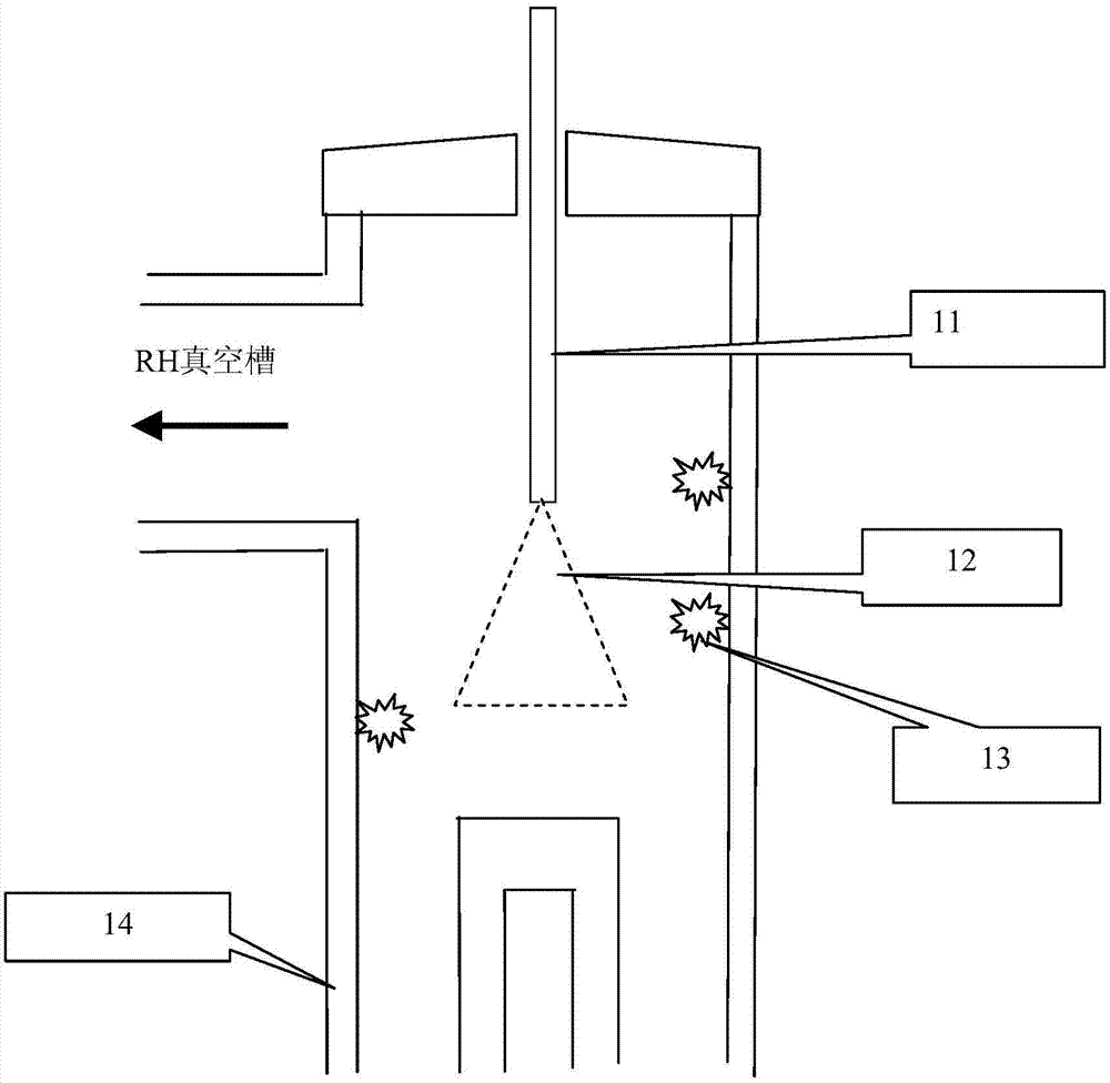
[0032] In the present invention, the RH top lance is used to spray pure oxygen to directly react with cold steel, which greatly improves the efficiency of removing cold steel. see figure 1 , the RH top gun 11 adopts pure oxygen to remove the cold steel, that is, the RH top gun 11 sprays the pure oxygen jet 12 to the cold steel 13 on the wall of the RH dipping tube 14 in the RH vacuum tank, because the pure oxygen directly interacts with the iron in the cold steel reaction, namely 2[Fe]+O 2 =2FeO and 4FeO+O2=2Fe 2 o 3 , the reaction is an exothermic reaction, and the calorific value is extremely high, and the reaction speed is fast. Therefore, direct use of pure oxygen to melt and remove cold steel can obtain a high efficiency of removing cold steel. In addition, the oxygen content in pure oxygen exceeds 99%...


PUM


Abstract

The invention discloses a RH cold steel removing method, and belongs to the field of external refining RH zone cold steel removing technology. The RH cold steel removing method is used for solving problems that conventional methods are long in cold steel removing time, and are unsafe. The RH cold steel removing method comprises following steps: operation preparation, wherein RH top lance is arranged at the top part of a RH furnace vacuum groove, the positions of the RH top lance can be adjusted, the RH top lance is connected with a device used for providing pure oxygen, and oxygen flow amount can be adjusted; and cold steel removing, wherein according to the different positions of cold steel in the vacuum groove, a plurality of spraying segments are set based on the positions of the RH top lance from high to low, pure oxygen flow is sprayed onto cold steel in the vacuum groove at each segment in sequence, pure oxygen flow amount and spraying time are adjusted at different segments, exothermic reaction of pure oxygen with ferric oxide in cold steel is realized, cold steel in the vacuum groove is removed via melting, and cold steel removing is completed after the last operation period. Top lance positions are set according to the height, the RH cold steel removing method is used for heat melting cold steel in different positions in the RH groove, cold steel removing efficiency is increased, cold steel removing time is shortened, and operation safety is increased because that pure oxygen contains no impurity.

Description

technical field [0001] The invention relates to the technology of removing chilled steel in the RH area of ​​refining outside the furnace, in particular to a method for removing chilled steel in the RH area. Background technique [0002] Cold steel refers to the molten steel and steel slag splashed in the vacuum tank during the vacuum treatment of the RH furnace, which solidifies for a long time and accumulates to form steel and slag polymers. [0003] The cold steel in the vacuum tank of the RH furnace will not only affect the vacuum degassing area, but also deteriorate the quality of the molten steel after refining in the RH furnace. Therefore, the cold steel in the vacuum tank of the RH furnace must be melted and removed, which is called RH decooling in the industry. steel. [0004] The existing RH cold steel removal technology mainly uses RH-KTB oxygen gun to inject gas to the cold steel, supplemented by air (the ratio of gas to air is about 1:1), and uses the high calo...

Claims


Application Information

Patent Timeline
Patent Type & Authority Applications(China)
IPC IPC(8): C21C7/10
Inventor 李晓强龚兴东郑建忠马志刚杨锐
Owner BAOSHAN IRON & STEEL CO LTD
Learn More