
Electrostatic spinning continuous collection device

An electrospinning and receiving device technology, which is applied in the field of continuous collection devices for electrospinning, can solve the problems of uncontrollable fiber shape and thickness, prolonging coagulation time, and reducing coagulation rate, so as to reduce coagulation time and discharge of waste liquid. , Improve solidification efficiency, improve the effect of utilization

Inactive Publication Date: 2015-07-15
GUANGXI TEACHERS EDUCATION UNIV
View PDF9 Cites 4 Cited by
  • Summary
  • Abstract
  • Description
  • Claims
  • Application Information

AI Technical Summary

Problems solved by technology

[0003] In the existing electrospinning device, when the solvent is not easily volatile, the solvent in the polymer solution is dissolved in the coagulation liquid in the water bath mainly through the docking of the water bath and the spraying device, so that the fibers are separated out. The shape and thickness of the fiber cannot be controlled. At the same time, the coagulation liquid in the water bath is a non-flowing fluid. After processing a part of the fiber, it is necessary to suspend the work of the electrospinning device and continue after replacing the coagulation liquid, so that the electrospinning work Discontinuous, unnecessary time wasted, and the coagulation rate will decrease after the coagulation solution in the water bath processes a part of the fibers, prolonging the coagulation time

Method used


Image

  • Electrostatic spinning continuous collection device
  • Electrostatic spinning continuous collection device
  • Electrostatic spinning continuous collection device

Examples


Embodiment Construction

[0031] The present invention will be further described in detail below in conjunction with the accompanying drawings, so that those skilled in the art can implement it with reference to the description.

[0032] It should be understood that terms such as "having", "comprising" and "including" as used herein do not entail the presence or addition of one or more other elements or combinations thereof.

[0033] The invention discloses a method for continuous collection of electrospinning, which is to atomize coagulation bath solution to carry out continuous collection of electrospinning.

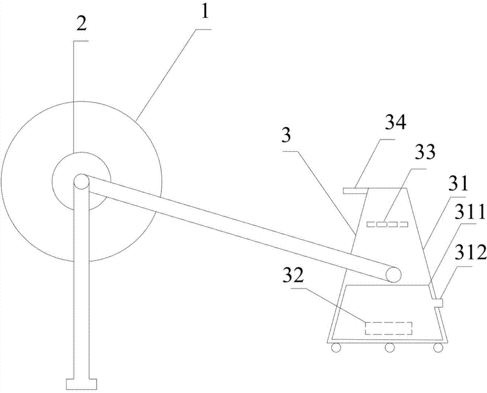
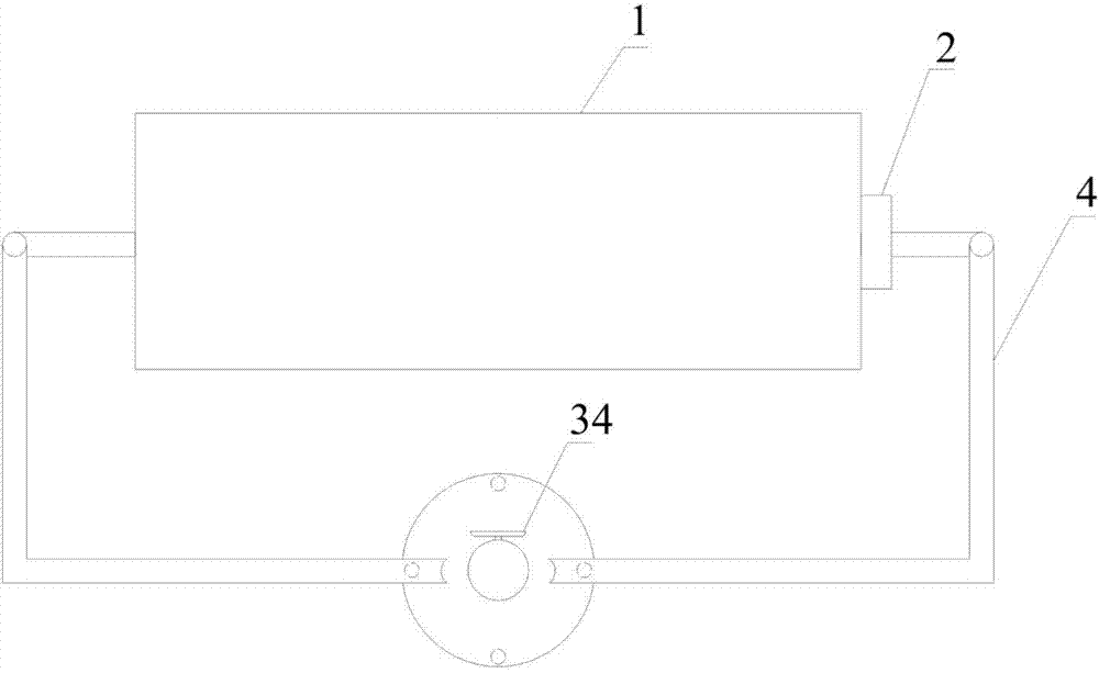
[0034] Figure 1-2 According to an implementation form of the present invention, a device for continuous collection of electrospinning is provided, including:

[0035] The receiving device 1 is cylindrical, and the two ends of the receiving device 1 are respectively fixed horizontally by brackets;

[0036] Motor 2, which is connected to the receiving device 1 and drives the receiving device 1...


PUM


Abstract

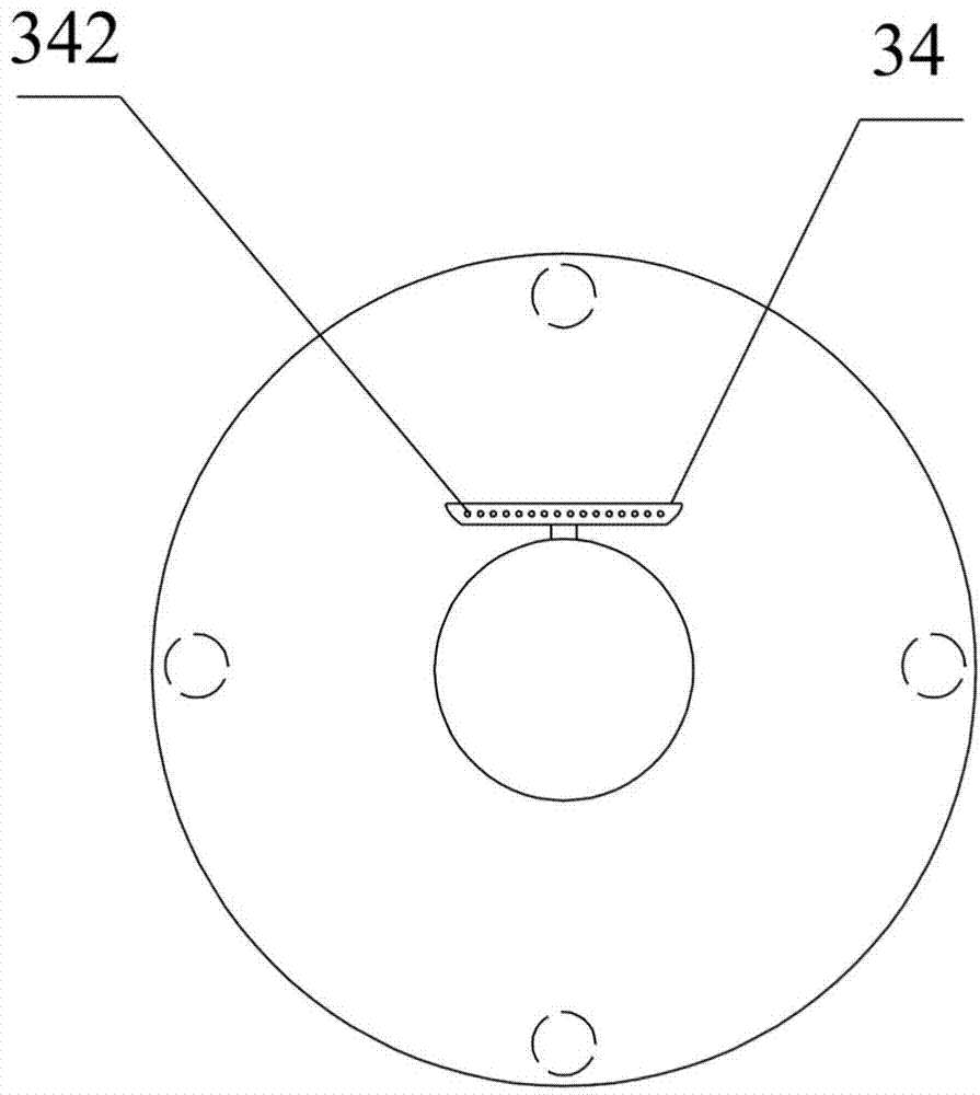
The invention discloses an electrostatic spinning continuous collection method. Coagulating bath solutions are atomized to carry out electrostatic spinning continuous collection, and are prevented from being replaced, and electrostatic spinning continuous collection is achieved. The invention further discloses an electrostatic spinning continuous collection device. The electrostatic spinning continuous collection device comprises a receiving device, a motor and a coagulating bath atomization device. The receiving device is cylindrical, and the two ends of the receiving device are horizontally fixed through supports respectively. The motor is connected with the receiving device. The coagulating bath atomization device is arranged in front of the receiving device, and comprises a shell, an atomizer, an exhaust fan and a nozzle. The shell is conical, hollow water containing space is arranged on the lower portion of the shell, and a water inlet communicated with the water containing space is formed in the outer wall of the lower portion of the shell. The atomizer is arranged in the shell. The exhaust fan is arranged on the upper portion of the shell. The nozzle is arranged on the upper portion of the shell, communicated with the shell and arranged to face the receiving device. The coagulating bath solutions are atomized through the coagulating bath atomization device, the utilization rate and coagulation efficiency of the coagulating bath solutions are improved, and waste liquid discharge is reduced.

Description

technical field [0001] The invention relates to the field of electrostatic spinning. More specifically, the present invention relates to continuous collection devices for electrospinning for use in situations where the solvent in the polymer solution is not volatile. Background technique [0002] Electrospinning is a special fiber manufacturing process. This method can produce polymer filaments with nanometer diameters. The basic principle can be simply summarized as the effect of electric field force on polymer solution or melt in a high-voltage electrostatic field. The jet spinning is carried out under the capillary or the end of the bubble to form a jet and fly to the receiving device. The general electrospinning device includes a high-voltage power supply, solution storage, spraying and receiving device, where the receiving device corresponds to the receiving of the fiber, and the jet reaches the receiving device. In the process of high stretching, the fibers become thi...

Claims


Application Information

Patent Timeline
IPC IPC(8): D01D5/00
CPCD01D5/0007D01D5/0076
Inventor 熊文朋贾永堂杨剑李延锋湛茹淇
Owner GUANGXI TEACHERS EDUCATION UNIV
Learn More